


EN
7
7
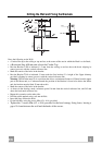
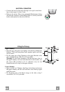
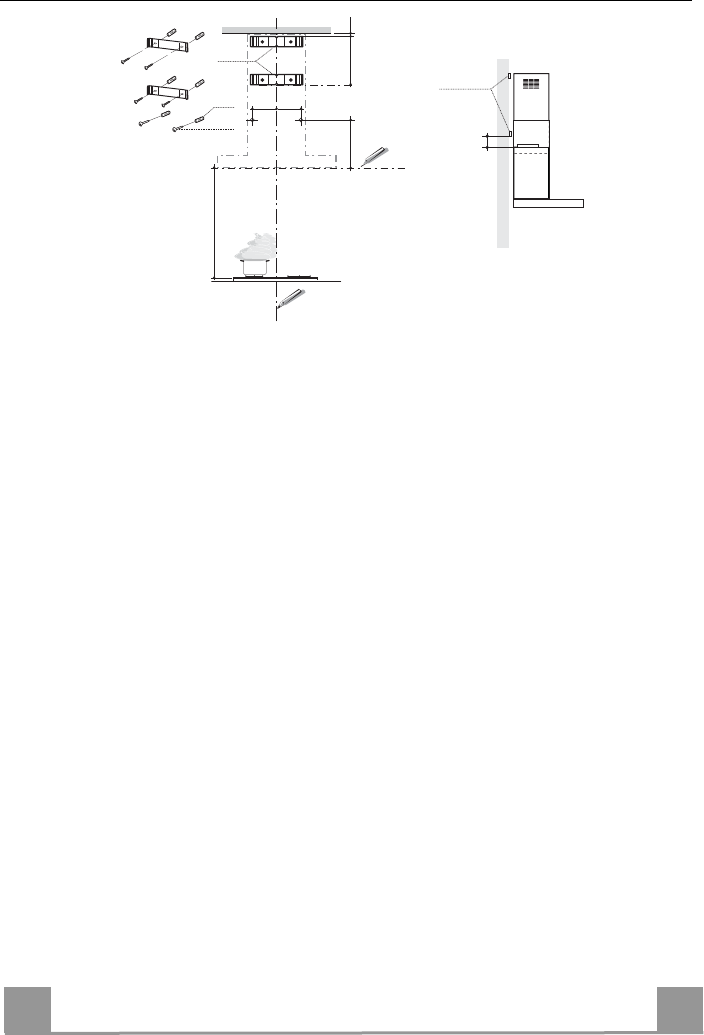
Drilling the Wall and Fixing the Brackets
11
12a
545
X
116
1÷2
116
650 min.
7.2.1
Min. 50mm
7.2.1
Draw the following on the Wall:
• a Vertical line up to the ceiling or top surface, at the centre of the area in which the Hood is to be fitted;
•
a Horizontal line: 650 mm min. above the Cooker Top.
• Rest the Bracket 7.2.1 as indicated, 1-2 mm from the ceiling or surface above the hood, aligning its
centre (grooves) with the vertical reference line.
• Mark the centres of the holes in the bracket.
• Rest the Bracket 7.2.1 as indicated, X mm under the first bracket (X = height of the Upper chimney
provided), aligning its centre (grooves) with the vertical reference line.
Warning: The Bracket must be in a position that allows a minimum distance of 50mm from the upper
part of the Motor unit, so if when measured the position of the Bracket is found to be below the Motor
unit, the bracket must be fitted 50 mm above this.
• Mark the centres of the holes in the bracket.
• As shown in the drawing, mark a reference point 116 mm from the vertical reference line, and 545 mm
above the horizontal reference line.
• Repeat this operation on the other side.
• Drill the points marked using a ø 8 mm drill bit.
• Insert the plugs 11 into the holes.
• Fix the brackets, using the screws 12a (4.2 x 44.4 ) provided.
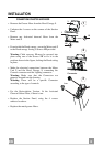
•
Tighten the 2 screws 12a (4.2 x 44.4) provided in the hood canopy fixing bores, leaving a
gap of 5-6 mm between the wall and the heads of the screws.