


32 www.pridemobility.com Jazzy 1133 Owner’s Manual Rev B 03-03
VSI CONTROLLER
The electronic controller is what you use to operate your power chair. It takes the battery voltage and sends it to the
appropriate system. The electronic controller enables you to move the power chair, as well as monitor battery
charge, electronic controller functions, and the condition of your electrical system. Also, it may be used to control
some optional systems such as power elevating seats and lights.
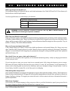
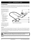
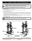
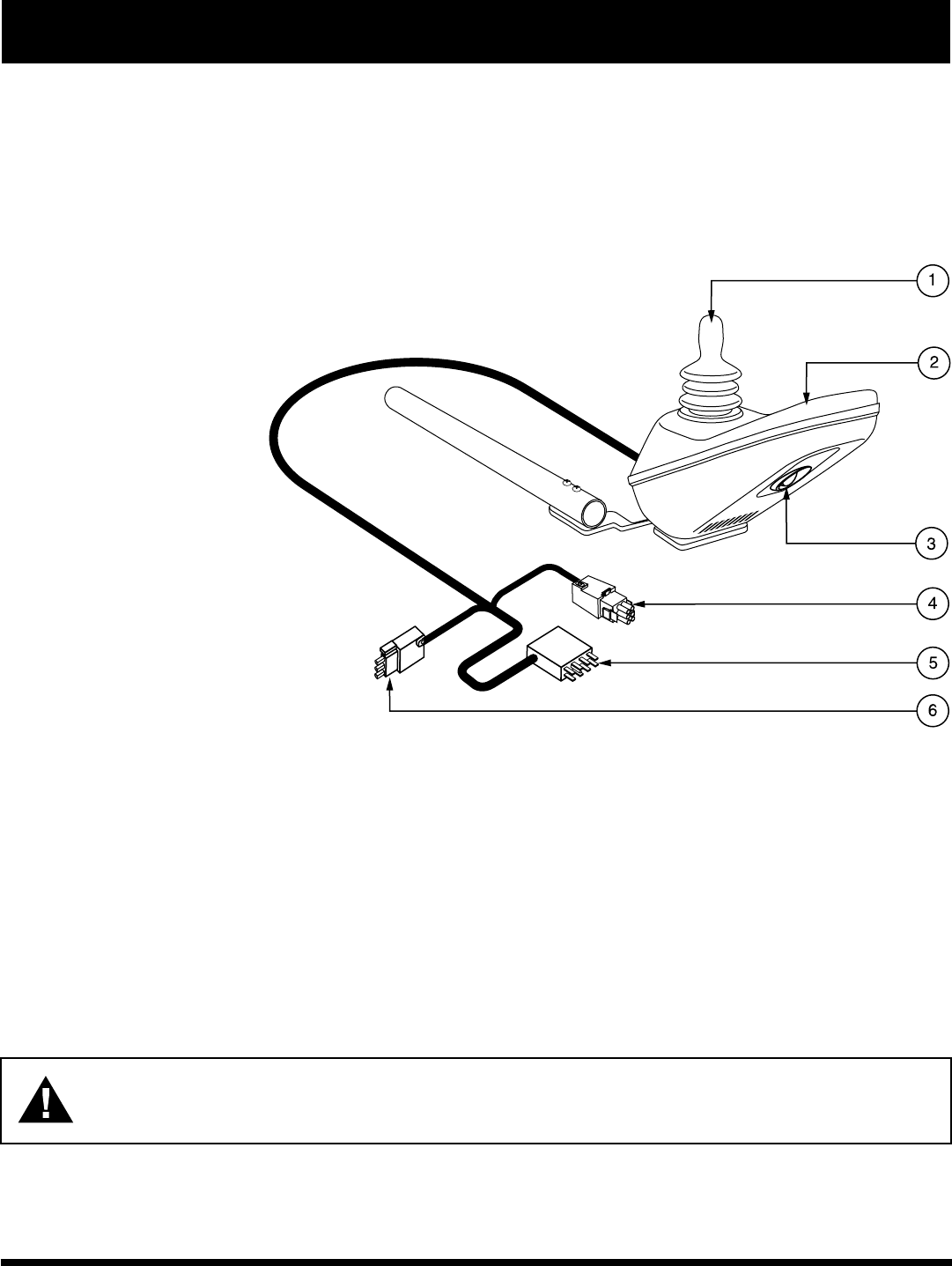
The VSI controller is an inte-
gral electronic controller. All
of the electronics necessary to
operate the power chair are
contained in one module. See
figure 27.
The VSI consists of:
1. joystick
2. keypad (see figure 28)
3. off-board charger/pro-
gramming socket
4. actuator connector
(for optional equipment
on some models)
5. controller connector
6. 3-pin charger inhibit
connector
Typically, the VSI is mounted
to one of the armrests and is
connected to the motors, bat-
teries, and the onboard charger
at the front battery box.
Joystick
The joystick controls the direction and speed of your power chair. When you move the joystick from the neutral
(center) position, the electromagnetic brakes release and allow your power chair to move. The further you push the
joystick from its neutral position, the faster your power chair moves. When you release the joystick and allow it to
return to the neutral position, you engage the electromagnetic brakes. This causes your power chair to decelerate
and come to a complete stop.
WARNING! If your power chair begins to move in an unexpected manner, immediately release the
joystick. Unless the joystick is damaged, this action should stop your power chair.
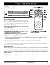
Keypad
The keypad is located in front of the joystick. It contains keys necessary to operate your power chair. See figure 28.
VIII. OPERATION
Figure 27. VSI Controller Assembly