


Jazzy 1133 Owner’s Manual Rev B 03-03 www.pridemobility.com 23
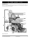
COMFORT ADJUSTMENTS
After becoming familiar with your power chairs operation, you may find the need to make some adjustments to
increase your comfort, such as seat height and angle, armrest angle, footrest height and angle, and the controllers
position. If your power chair is equipped with a Synergy Seat or the Versa Tilt, refer to the information provided in
separate manuals. If your power chair is equipped with a medium back, a high back, or a reclining seat, refer to the
following information.
WARNING! If your Jazzy was configured at your authorized Pride provider or service center, please
consult your healthcare professional before changing the seat position or making any other
adjustment. Some adjustments may degrade your Jazzys performance and safety by changing
its center of gravity.
You may need the following to make comfort adjustments:
n metric/standard hex key set
n metric/standard socket set and ratchet
n adjustable wrench
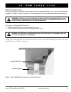
Seat Height and Seat Angle Adjustment
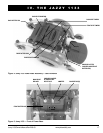
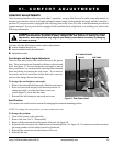
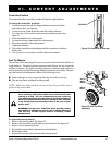
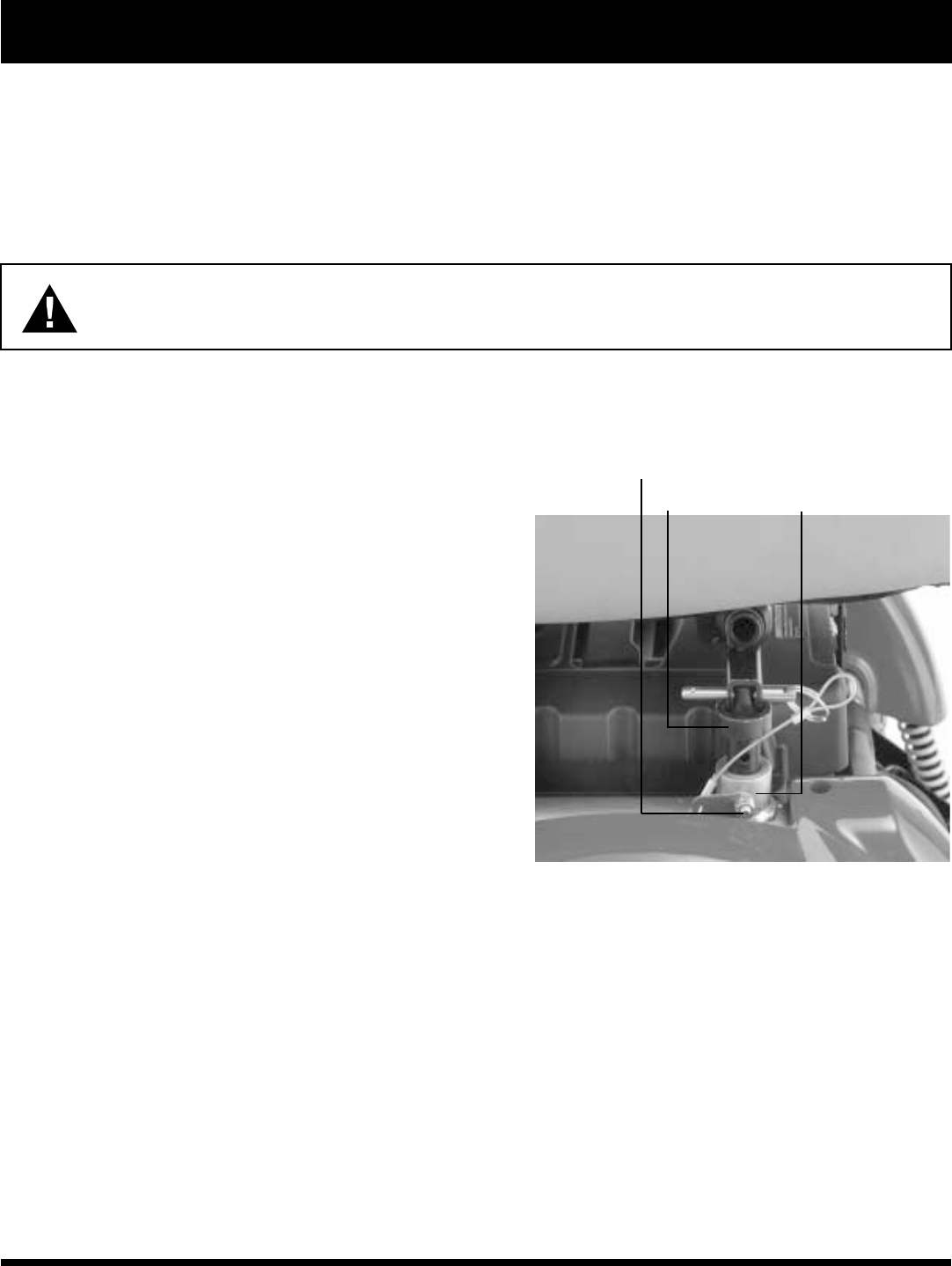
There are four steel towers that connect the seat to the power
base. These seat towers are fastened to the base with nuts and
bolts. See figure 17. You can change the seat height to one of
three positions in 1-in. increments by removing these nuts and
bolts and raising or lowering the seat towers. If you raise or
lower only one set of seat towers (either front set or rear set),
you can also change the seat base angle.
To change the seat height or seat angle:
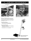
1. Remove the nuts and bolts from each of the four seat towers.
2. Raise or lower each seat pin to the desired position. To
change the angle, set either the front or rear seat
towers higher or lower than the other.
3. Reinstall the ball detent pin into each seat tower.
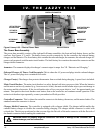
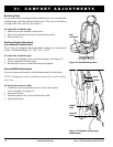
Seat Position
You can move the seat forward or rearward by changing the extrusion mounting position.
NOTE: To change the seat position, you must remove the seat.
To change the position:
1. Turn off the power to the controller.
2. Remove the seat. See V. Disassembly.
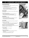
3. Remove both extrusions from the bottom of the seat. See figure 18.
4. Reposition the extrusions on a different set of mounting holes. See figure 18. You must move both extrusions
the same number of holes either forward or backward.
5. Reinstall the extrusions onto the bottom of the seat.
6. Reinstall the seat.
Figure 17. Seat Tower Detail
VI. COMFORT ADJUSTMENTS
SEAT TOWER FASTENERS
SEAT TOWER
SEAT PIN