


Jazzy 1133 Owner’s Manual Rev B 03-03 www.pridemobility.com 27
Controller Position
You can position the controller for either left-hand or right-hand use.
To change the controller position:
1. Unplug the controller and the charger inhibit connectors from the
back battery box. See figure 6.
2. Cut the wire tie(s) that attach the controller cable to the seat.
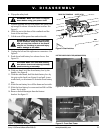
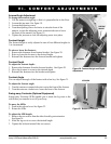
3. Use a hex key to loosen the setscrew underneath the armrest. See
figure 25.
4. Slide the controller out of the armrest.
5. Loosen the setscrew underneath the other armrest.
6. Place the controller in the other armrest.
7. Tighten the setscrew.
8. Plug in the controller and the charger inhibit connectors to the back
battery box.
9. Use a wire tie to secure the controller cable to the armrest.
Anti-Tip Wheels
The anti-tip wheels are designed to give your power chair increased stability on
rough surfaces. The anti-tip wheels are preset at the factory for use on smooth
surfaces or indoors. If you plan on using your power chair on rough surfaces, it
may be necessary to adjust the anti-tip wheels to better suit your needs. The anti-
tip wheels may need adjustment if either of the following occur:
n When coming to a stop, your power chair tips forward excessively.
n The anti-tip wheels constantly rub the ground.
NOTE: Make sure that each drive tire has at least 30 psi and the user is
seated in the power chair.
WARNING! The higher you raise the anti-tip wheels, the
more tendency your power chair has to tilt forward when
coming to a stop. You can compensate for this by having
your authorized Pride provider make a small adjustment to
the pre-programmed deceleration setting in the controller
or by moving the seat assembly further to the rear of your
power chair.
WARNING! Consult your authorized Pride provider before
attempting to change the anti-tip wheel height! Changing
the anti-tip wheel height affects handling under
deceleration!
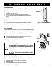
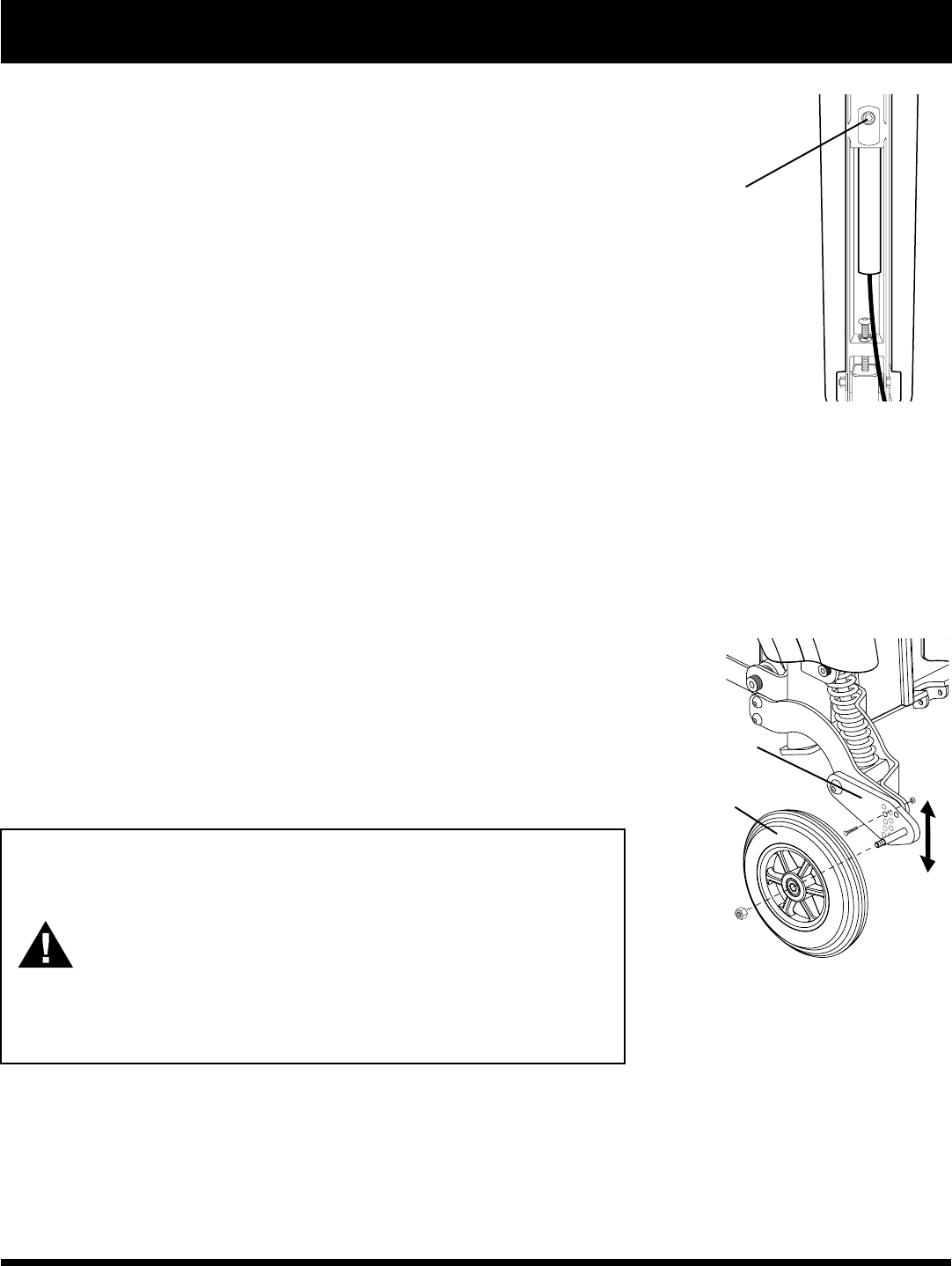
To adjust the anti-tip wheels:
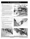
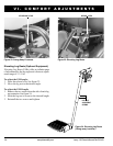
1. Remove the anti-tip wheel. See figure 26.
2. Remove the nut and bolt on the anti-tip wheel bracket. See figure 26.
3. Raise or lower the anti-tip wheel.
4. Reinstall the nut and bolt on the anti-tip wheel bracket.
5. Reinstall the wheel.
6. Repeat the same procedure for the other anti-tip wheel.
VI. COMFORT ADJUSTMENTS
Figure 25. Underside of Armrest
SETSCREW
Figure 26. Anti-Tip Wheel
Assembly
ANTI-TIP
WHEEL
ANTI-TIP
WHEEL
BRACKET