


18 www.pridemobility.com Jazzy 1133 Owner’s Manual Rev B 03-03
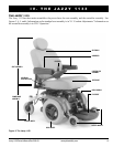
The Power Base Assembly
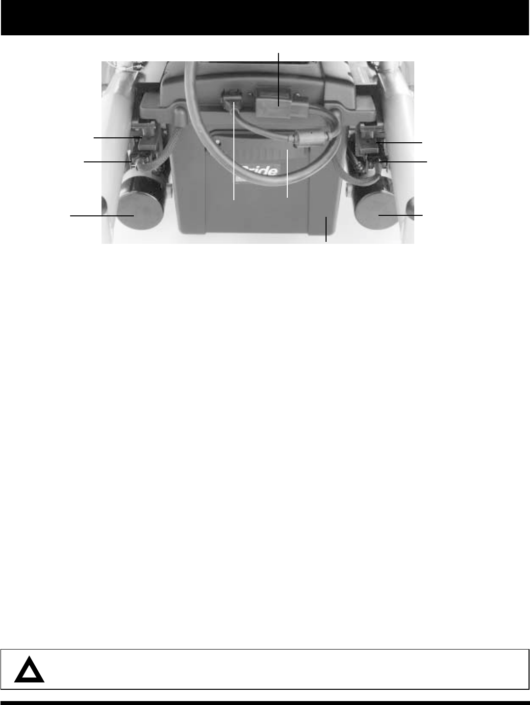
The power base assembly consists of the right and left frame assemblies, the front and back battery boxes, and the
seat bars. See figures 4, 5, and 6. The battery boxes provide connectivity for the controller, the onboard battery
charger, and the batteries. The front battery box contains the onboard charger, the ammeter, the onboard charger AC
power cord receptacle, and the main circuit breaker. The back battery box contains the controller connector and the
charger inhibit connector.
Ammeter: The ammeter displays the chargers current output in amps. See VII. Batteries and Charging.
Onboard Charger AC Power Cord Receptacle: This is where the AC power cord plugs into the onboard charger.
The AC power cord plugs into a standard wall outlet.
Charger Fuse(s): The charger fuse protects the ammeter from overload during charging. A spare fuse is included.
Main Circuit Breaker: The main circuit breaker is a safety feature built into your power chair. When the batteries
and the motors are heavily strained (e.g., from excessive loads), the main circuit breaker trips to prevent damage to
the motors and the electronics. If the circuit breaker trips, allow your power chair to rest for approximately one
minute. Then push in the circuit breaker reset button, turn on the controller, and continue normal operation. If the
main circuit breaker trips repeatedly, contact your authorized Pride provider.
Controller Connector: This is where the controller connects to the battery, the motors, and the motor brakes. The
standard controller connector is shown.
Charger Inhibit Connector: The controller is equipped with a charger inhibit. The charger inhibit enables the
onboard battery charger to disable the controller during charging. The charger inhibit connector is coded with
colored dots. The dots are positioned so that you can align the flat side of the male connector with the flat side of
the female connector before making the connection.
CAUTION! Failure to properly align the connectors can result in damage to the controller, the
onboard charger, and the connectors.
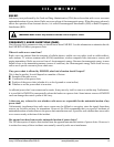
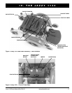
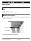
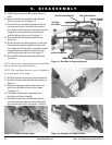
Figure 6. Jazzy 1133 — Back of Power Base
CONTROLLER CONNECTOR
CHARGER INHIBIT
CONNECTOR
MOTOR/BRAKE
ASSEMBLY
LEFT MOTOR
CONNECTOR
RIGHT MOTOR
CONNECTOR
MOTOR/BRAKE
ASSEMBLY
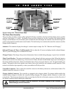
IV. THE JAZZY 1133
BACK BATTERY
BOX GRIP
BACK BATTERY BOX
LEFT BATTERY BOX
RELEASE LEVER
RIGHT BATTERY BOX
RELEASE LEVER