


Go-Chair www.pridemobility.com 17
III. YOUR GO-CHAIR
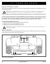
ELECTRICAL COMPONENTS
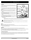
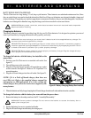
The electrical components are located on the power base. The main circuit breaker is located on the front of the battery
box. The controller connector is located on the back of the power base. See figure 6.
Controller Connector: This is where the controller connects to the batteries and the motors.
Battery Box Charger Port: This enables you to charge the batteries when the battery box is removed from the power
base. See VI. “Batteries and Charging.
NOTE: The Go-Chair battery box can be charged on or off of the power base. The battery box charger port
should only be used when the battery box has been removed from the power base.
Main Circuit Breaker: The main circuit breaker is a safety feature built into your Go-Chair. When the batteries and the
motors are heavily strained (e.g., from excessive loads), the main circuit breaker trips to prevent damage to the motors and
the electronics. If the circuit trips, allow your Go-Chair to “rest” for approximately one minute. Next, push in the circuit
breaker button, turn on the controller, and continue normal operation. If the main circuit breaker continues to trip repeatedly,
contact an authorized Pride Provider.
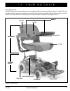
Figure 6. The Go-Chair Power Base
FRONT SECTION
BATTERY BOX
CIRCUIT BREAKER
REAR SECTION
SEAT PEDESTAL
CONTROLLER CONNECTOR
FREEWHEEL LEVER
BATTERY BOX CHARGER PORT