,.·
R-4104.A
ADJUSTMENT
5. Cantllring
the
Tube
Attmching and Stago Attaching
Paru
6. Cantering
of
OptiCllll
System in
the
Microscope Base
5-3.
Using positioning tool 125141,
to
check the position
of
substage and condenser mount
1)
As
shown
in
Fig. 1 (P. 3), bring the
part@,
of
the tool onto the condenser attaching
surface, and the
part@
onto the stage
attaching surface.
2) Raise the condenser attaching surface to
make sure that the part
@ enters the
part
@.
3)
If
it
does not, make adjustment by
means
of
@
x4.
6. Cantering
of
Optical System
in
the Microscope Base
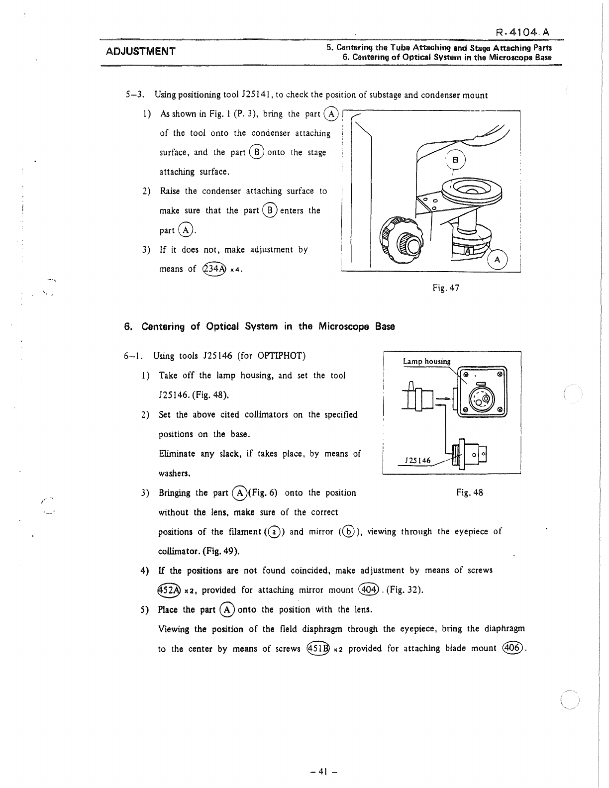
6-l.
Using tools 125146 (for OPTIPHOT)
1) Take
off
the lamp housing, and set the too!
125146. (Fig. 48).
2)
Set the above cited collimators on the specified
positions on the
base.
Elimina te any slack, if takes place, by means of
washers.
3) Bringing the part
@CFig.
6) onto the position
without the lens, make sure
of
the correct
Fig. 47
125146
Fig.
48
positions
of
the filament
(G))
and mirrar
(@),
viewing through the eyepiece
of
collima
tor. (Fig. 49 ).
4)
If
the positions are
not
found coincided, make adjustment by means
of
screws
@
x:i,
provided for attaching mirror mount
@.(Fig.
32).
5)
P1ace
the part
@onto
the positfon with the lens.
Viewing the position
of
the field diaphragm through the eyepiece, bring the diaphragm
to the center by means
of
screws @ x 2 provided for attaching biade mount
@.
-41
-
~.
;


