


155
CHAPTER 6 COMMUNICATIONS AMONG CPU MODULES
6
6.1 Communications Using the CPU Shared Memory
6.1.3 Communications by programs using the CPU shared memory
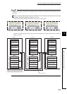
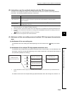
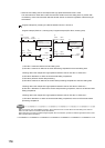
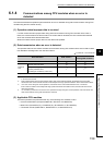
(b) Preventing inconsistency of data exceeding 32 bits
• When the user setting area is used
The read instruction reads data in order starting from the start address to the end address of the user
setting area. On the other hand, the write instruction writes data in order starting from the end address to
the start address of the user setting area.
To prevent data inconsistency, set an interlock device at the start of data to be communicated.
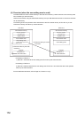
Ex.
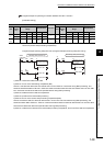
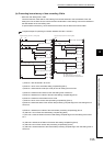
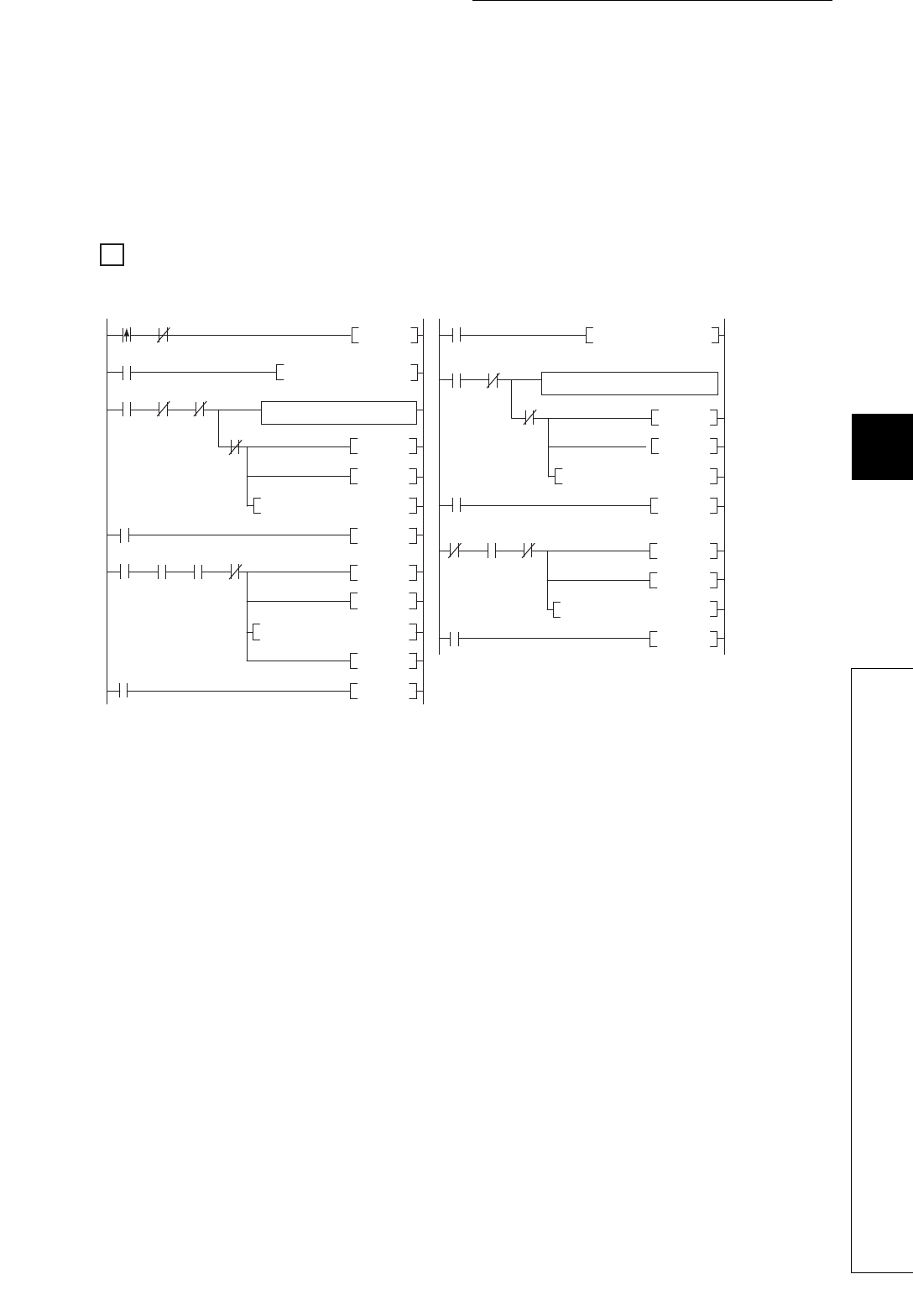
Program example for providing an interlock between CPU No.1 and No.2
1) CPU No.1 sets send data in D1 to D9.
2) CPU No.1 turns on the send data setting complete flag (D0.0).
3) CPU No.1 writes the send data (D1 to D9) to the user setting area of its own.
4) CPU No.2 reads the send data from the user setting area of CPU No.1.
5) CPU No.2 detects the on status of the send data setting complete flag (D0.0).
6) CPU No.2 reads the receive data from D1 to D9.
7) CPU No.2 turns on the receive data processing complete flag (D10.0).
8) CPU No.2 writes the status of the receive data processing complete flag to the user setting area of
CPU No.2.
9) CPU No.1 detects the on status of the receive data processing complete flag (D10.0.
10) CPU No.1 turns off the send data setting complete flag (D0.0).
11) CPU No.1 writes the status of the send data setting complete flag to the user setting area of CPU
No.1.
12) CPU No.2 detects the off status of the send data setting complete flag (D0.0).
13) CPU No.2 turns off the receive data processing complete flag (D10.0).
14) CPU No.2 writes the status of the receive data processing complete flag to the user setting area of
CPU No.2.
M0
M2
M2 D0.0 D10.0
M2
M4
M3
D0.0 D10.0
M2
M1
M1
M0
D0.0
M2
D10.0
M3
D0.0 D10.0 M1
M1
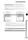
FROM H3E1 H900 D10 K1
SET M2
Set send data in D1 to D9.
SET D0.0
SET M1
SP.TO H3E0 H900 D0 K10 M3
SP.TO H3E1 H900 D10 K1 M2
SP.TO H3E1 H900 D10 K1 M3
RST M1
RST D0.0
SET M1
SP.TO H3E0 H900 D0 K1 M4
RST M2
RST M1
SET D10.0
SET M1
SET M1
RST M1
RST M1
M0: Read command
M1: S.TO instruction in-execution flag
M2, M3: S.TO instruction completion device
RST D10.0
Operation using the receive data
(D1 to D9)
Program example (CPU No.1, sending side) Program example (CPU No.2, receiving side)
FROM H3E0 H900 D0 K10
1)
2)
3)
4)
11)
12)
13)
14)
5)
6)
7)
8)
9)
10)