


149
CHAPTER 6 COMMUNICATIONS AMONG CPU MODULES
6
6.1 Communications Using the CPU Shared Memory
6.1.2 Communications by auto refresh (using the multiple CPU high speed transmission area)
Ex.
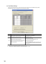
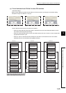
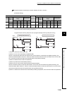
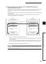
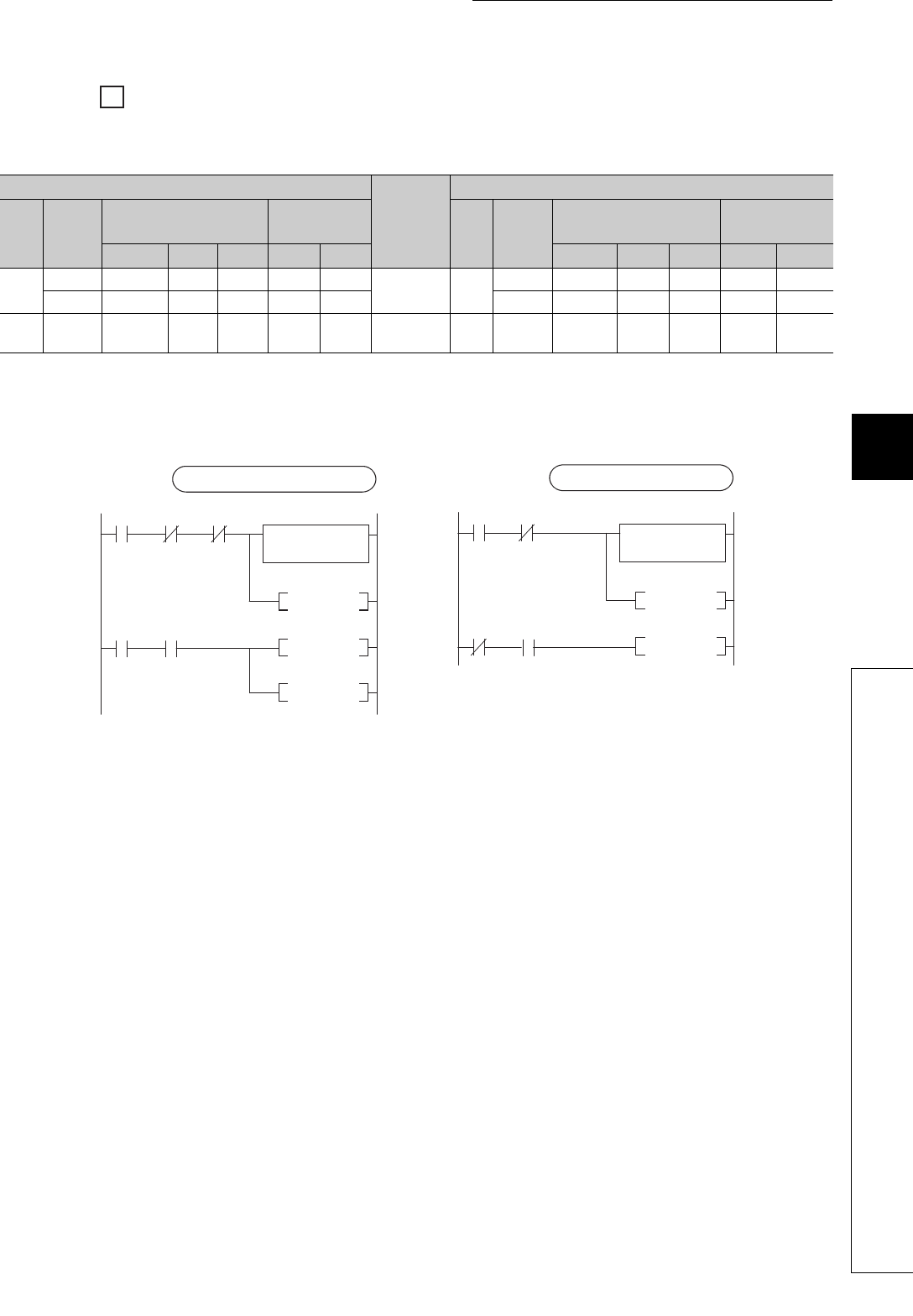
Program example for providing an interlock between CPU No.1 and No.2
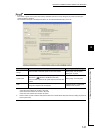
[Parameter setting]
Use M0 as an interlock device of CPU No.1 (data setting complete bit) and M32 as an interlock device of
CPU No.2 (receive data processing complete bit).
Program example (sending side) (CPU No.1)Program example (receiving side) (CPU No.2)]
1) CPU No.1 stores send data to D0 to D9.
2) CPU No.1 turns on the data setting complete bit (M0).
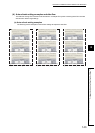
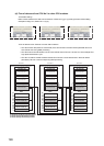
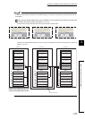
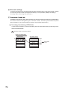
CPU No.1 transfers the data to the auto refresh area in its own CPU No.1 send area during END processing, and
sends the transferred data to CPU No.2. CPU No.2 reads the received data from the auto refresh area in its own CPU
No.1 send area and stores the data to the specified device during END processing.
3) CPU No.2 detects the send data set complete bit.
4) CPU No.2 performs the receive data processing.
5) CPU No.2 turns on the receive data processing complete bit (M32).
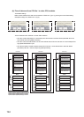
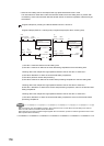
CPU No.2 writes the data of to the auto refresh area in its own CPU No.2 send area during END processing, and
sends the written data to CPU No.1. CPU No.1 reads the received data from the auto refresh area in its own CPU No.2
send area and stores the data to the specified device during END processing.
6) CPU No.1 detects the on status of the receive data processing complete bit, and turns off the data set complete bit.
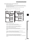
CPU No.1 auto refresh setting
Direction
CPU No.2 auto refresh setting
PLC
Setting
No.
CPU Specific Send
Range
Auto Refresh
PLC
Setting
No.
CPU Specific Send
Range
Auto Refresh
Points Start End Start End Points Start End Start End
PLC
No.1
1 2 01M0M31
PLC
No.1
1 2 0 1 M0 M31
2 10 2 11 D0 D9 2 10 2 11 D0 D9
PLC
No.2
1 2 01M32M63
PLC
No.2
12 01M32M63
4)
3)
7)
5)
SET M32
RST M32
M32
M32M0
M0
(Receiving side (CPU No.2))
Operation using the
receive data
(D1 to D9)
Write
command
1)
2)
6)
SET M0
RST M0
RST M100
M32M0
M32M0M100
(Sending side (CPU No.1))
Setting the send
data to D0 to D9