


Positioning Control Actual Positioning 5
5-7
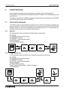
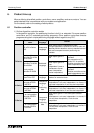
5.2.4 Operation
Now that your program has been written, check the communication cables between the FX
2N
-
20GM and PC, then download your program to the FX
2N
-20GM. Make sure that the GM unit is
in ‘MANU’ mode before download, or it will be impossible to communicate.
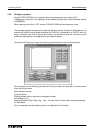
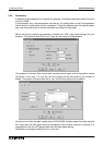
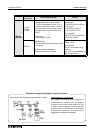
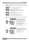
In VPS, start the Monitor mode by clicking the Monitor icon on the tool bar, shown below.
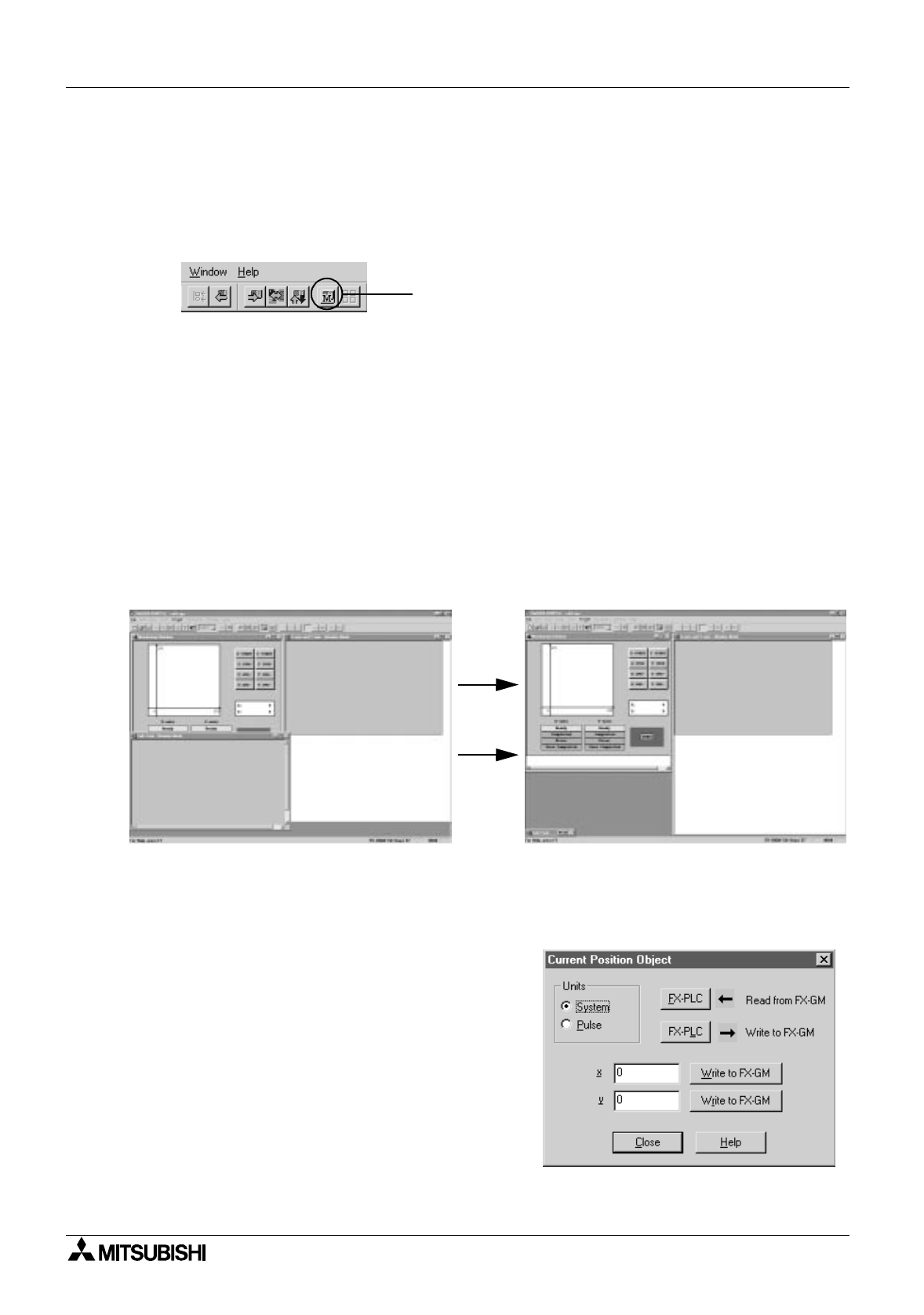
The Monitor mode screen will appear. Here, the flow icon menu and program map have been
removed. Three windows are displayed;
Monitoring window: This is the window you created, and will use to control the FX
2N
-20GM and
view the resulting locus.
Sub-task - Monitor mode: This window in not needed as we do not use any sub routines in our
programs, it can be minimized to create more space on the screen.
X-axis and Y-axis - Monitor mode - At first this window will be empty, but as soon as you start
your program, the flow chart will appear, and scroll through, keeping the live instruction
highlighted in red.
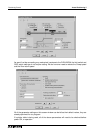
After minimizing the Sub-task monitor window, resize the Monitoring window and then the X-
axis and Y-axis window.
Now you are ready to begin.
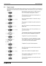
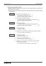
Firstly set the start point, this can be done be either using the X and Y axis JOG buttons, or by
double clicking on the current position display.
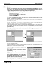
Double clicking the current position display brings
up this window;
For X, replace 0 with 50, and click on the ‘Write to
FX-GM’ button.
For Y, replace 0 with 125, and click on the ‘Write to
FX-GM’ button.
As you write that data to the GM, you will see a
red line being drawn on the plot in the Monitoring
window. This shows the current position.
We want a clean plot area to begin with, so double
click on the plotting area, and click on the clear button.
Monitor icon