


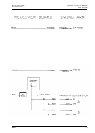

Description of control unit MEL64/65
Service manual M695
09/93 3077-HWE
Doc code 636 718
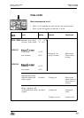
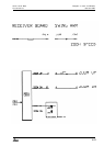
Control-LEDs
24V supply
Limitation of excess
current
10V supply
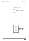
On the panel board:
10V OK:
green LED shines
>5A on 24V (PGND):
yellow LED shines
Fuse interrupted:
red LED shines
and on the function display:
5V
OK:
green LED shines
The 24V supply powers the servo board via the receiver board, and the
microscope via the swingann.
The fuse for the unstabilized main supply voltage is on the panel board
(6.3AT). The red LED indicates
a
burnt fuse.
The loading at maximum lamp
brightness
is about 3.25A. The yellow LED
on the panel board indicates switching off as a result of excess current (5A)
at PGND.
A switching regulator on the panel board reduces the 24V to 10V. The power
for the potentiometer (5V) is derived from it. The 5V regulator on the
RECEIVER BOARD is supplied with 10V.
5-6