


Service Manual M695 Testset
Doc code 638 718
09/93 3077-HWE
Test set M695/M680 - stock no. 566 152
Enables defective
assemblies to be
identified
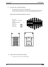
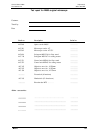
Contents of test set
Procedure for fault
location
See section 4
Cause in footswitch?
• Test box, stockno. 566 146
• Service cable M695/M680, stock no. 566 148
• Service handswitch, stock no.
566
147
• Foot- or handswitch
• Swingann
• Control unit MEL61/62 and MEL64/65
• X- or Y-gear MSV138 (M680 only)
• M695/M680 microscope
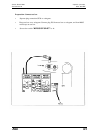
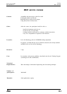
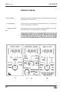
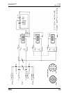
1.
Introduce the test box between the swingarm and the microscope - Plug
connections JP36 and JP37.
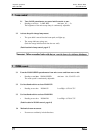
2.
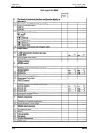
Inspect the voltages and currents of the POWER SUPPLY as described
in Section 4.
3.
Substitute service handswitch for footswitch, observe signal voltages, and
also monitor LEDs on control unit.
4.
Observe the signal voltages of the defective function (MICROSCOPE
CONTROL or XY-gear) - as described in Section 4.
Cause in microscope of
in XY-gear?
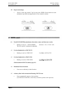
5. Separate the microscope or the XY-gear, as appropriate, from the test box,
and observe the signal voltages which flow from the control unit through
the swingann.
Cause in control unit or
swingarm?
6.
Use service cable to bridge swingarm, and observe signal voltages from
control unit.