


Service Manual M695 Testset
Doc code 638 718
09/93 3077-HWE
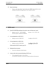
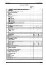
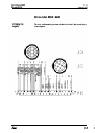
The test box:
three multimeters
Digital voltmeters
Supply for digital
voltmeter
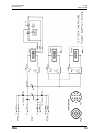
Circuit diagram on
page 18-5
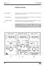
One digital voltmeter is assigned to each of the functions
POWER SUPPLY,
MICROSCOPE CONTROL and XY-GEAR. The signals reach the measuring
instrument through a rotary switch.
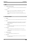
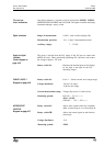
Range of measurement:
Measurement precision:
Auxiliary voltage:
1.999V - with overflow display (OL)
1% +- 1 digit, 2 measurements/second
7 . . . 15VDC
The power is derived from the 24V supply of the XY-gear (at control unit
MEL61/62 only). Three galvanically-separating DC converters each reduce
the voltage to approx. 12V each.
Rotary switch S1:
Displaces the decimal point on the display
by one digit to the right for the 24V -
measuring ranges.
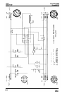
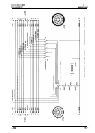
POWER SUPPLY
Diagram on page 18-6
Rotary switch S1:
Voltage distributor:
Level 1 ... Selects current- and voltage ranges.
1/10 for 12V range
1/100 for 24V ranges
Current measurement range: Voltage drop across 0.1 ohm resistor.
Measuring ground:
PGND - 24V
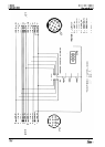
MICROSCOPE
SENS - PGND
GND-XY - 12V / 24V
XY-GEAR
MICROSCOPE
CONTROL
Diagram on page 18-7
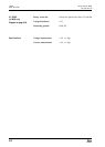
Rotary switch S3:
Rotary switch S2:
Selects those signals which are assignable
either to microscope A or to microscope B.
Selects the control signals to and from the
microscope.
Voltage distributor:
1/10
Measuring ground: SENS