


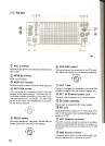

@ 1 MHz step switch
This switch is used to determine if the UP/DOWN
switches will function in 1 MHz steps or only thru the
amateur bands. When the 1 MHz step position is
selected, the 1 MHz indicator will light.
@ TUNING dial (VFO)
Rotate the knob to select the desired frequency. Fast
tuning is possible by rotating the knob rapidly. This con-
trol may also be used to select the desired memory
channel. The dial drag is adjustable by holding the out-
side knob and turning the inside knob clockwise to in-
crease drag, and counterclockwise to decrease drag.
The table in section 6-1, CRYSTAL FILTER INST AL-
LA TION on page 27 shows the bandwidth of each
switch setting. Note the differences when the option-
al filters are installed. The YK-88C is used in the "N"
position and the YK-88SN in the "M 1" position.
Notes: -
1. During transmit the wide filter position is selected
regardless of the position of the SELECTIVITY
switch.
2. When in the FM mode the bandwidth is always 15
kHz, regardless of the position of the SELECTIVI-
TY switch.
3. When the SELECTIVITY switch is set to N or M 1,
and no optional filters have been installed, there will
be no sound from the speaker. Refer to the option-
al filter installation procedure in the rear of this
manual for information on installation of these
options.
@ Program keys
M"'V: Used to recall a frequency from memory
to the VFO.
SCAN: Pressing during VFO operation will initiate
program scan, and pressing during memory
operation will initiate memory scan. Press-
ing during scan operation will cause the
scan speed to toggle between 2 speeds,
fast and slow.
CLEAR: Used to cancel memory storage operations,
or to cancel an entry during direct keyboard
entry of frequency using the ENT key.
VFO/M: Used to switch between memory or VFO
operations.
M.IN: Used to enter data into a memory channel.
ENT: Used to directly enter a frequency from the
numeric keypad.
@ AGC switch
This switch selects the operating time constant of the
AGC (Automatic Gain Control) circuit during receive.
When the AGC switch is set to SLOW, the receiver
gain and S-meter readings will react slowly to large in-
put changes, and when set to FAST, the receiver gain
and S-meter will react quickly to changes in the input
signal level.
The normal position when using all modes is the SLOW
position. When working weak signals, or high speed
CW you might wish to use the FAST position.
Note:
This switch is disabled during FM operations.~~"':
@ PHONES jack
Output terminal for headphones.
@ NOTCH switch
When this switch is ON, the notch filter is activated.
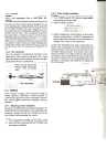
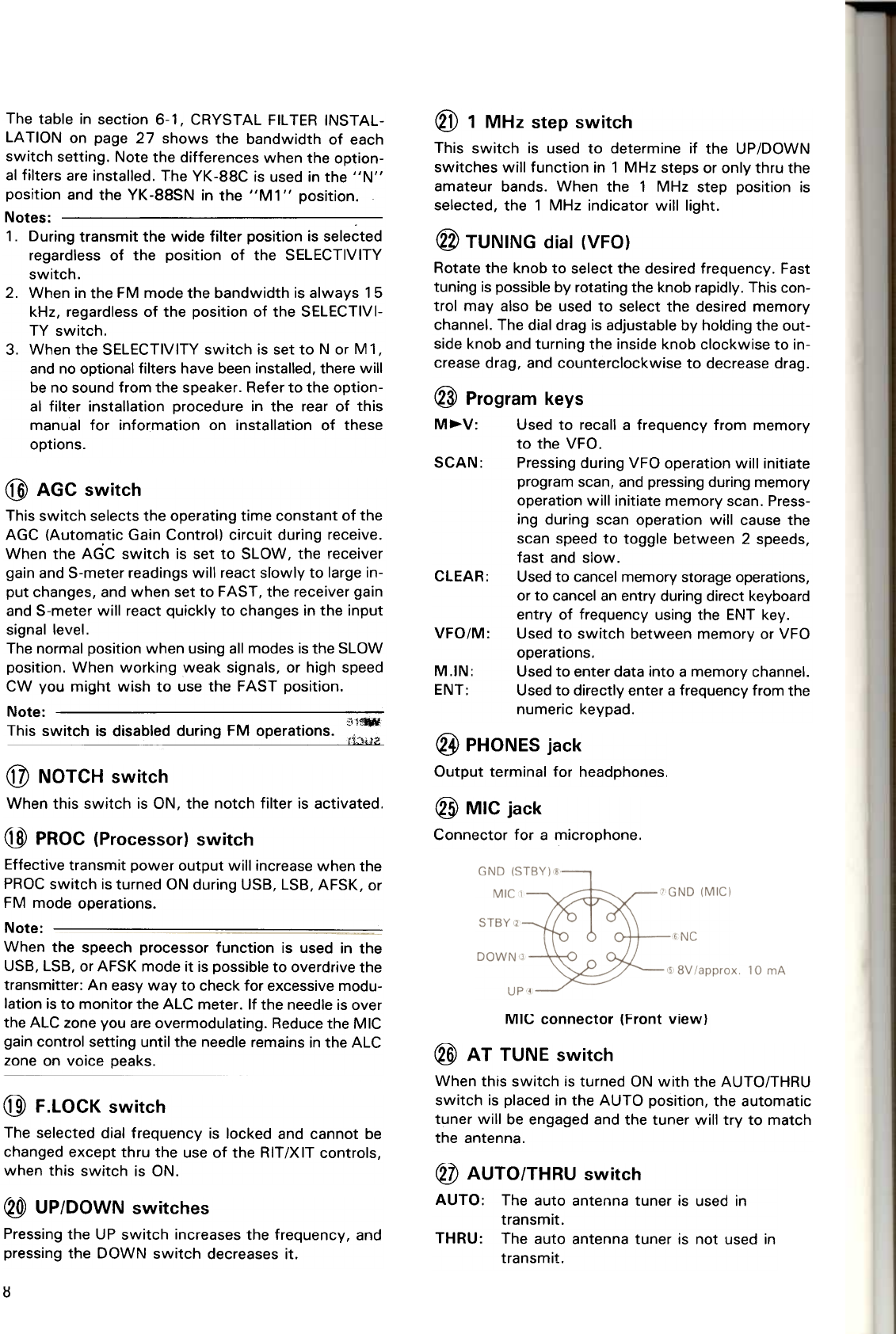
@ MIC jack
Connector for a microphone.
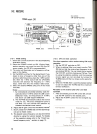
@ PROC (Processor) switch
Effective transmit power output will increase when the
PROC switch is turned ON during USB, LSB, AFSK, or
FM mode operations.Note:
When the speech processor function is used in the
USB, LSB, or AFSK mode it is possible to overdrive the
transmitter: An easy way to check for excessive modu-
lation is to monitor the ALC meter. If the needle is over
the ALC zone you are overmodulating. Reduce the MIC
gain control setting until the needle remains in the ALC
zone on voice peaks.
MIC connector (Front view)
@ AT TUNE switch
When this switch is turned ON with the AUTO/THRU
switch is placed in the AUTO position, the automatic
tuner will be engaged and the tuner will try to match
the antenna.
@ F.LOCK switch
The selected dial frequency is locked and cannot be
changed except thru the use of the RIT/XIT controls,
when this switch is ON.
~ UP/DOWN switches
Pressing the UP switch increases the frequency, and
pressing the DOWN switch decreases it.
@ AUTO/THRU switch
AUTO: The auto antenna tuner is used in
transmit.
THRU: The auto antenna tuner is not used in
transmit.
I:!