


Thank you for purchasing the new TS-440S tran-
sceiver. Please read this instruction manual carefully
before placing your transceiver in service. This unit has
been carefully engineered and manufactured to rigid
quality standards, and should give you satisfactory and
dependable operation for many years.
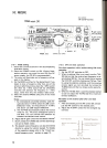
This Instruction Manual covers the TS-440S,
with and without AT (Automatic Antenna
Tuner) unit. When there are differences in
operation, separate instructions will be given for
each model. Illustrations show the TS-440S
with AT unit.
~
The following explicit definitions apply in this manual:
Note: If disregarded, inconvenience only, no risk
of equipment damage or personal injury.
Caution: Equipment damage may occur, but not per-
sonal injury.
CONTENTS
1. FEATURES. 3 4. CIRCUIT DESCRIPTION 20
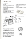
2. INSTALLATION 4 4-1. GENERAL DESCRIPTION 20
2-1. PRECAUTIONS 4 4-2. TRANSMITTER SECTION '...'.'.'.' 20
2-2. FIXED STATION 4 4-3. RECEIVER SECTION , 20
2-2-1. Interconnection 4 4-4. CIRCUIT BOARD DESCRIPTION 20
2-2-2. Grounding 4 4-4-1. RF unit (X44-1680-00) ,. 20
2-2-3. Antenna 5 4-4-2. IF unit (X60-1300-00) 20
2-2-4. Key connection 5 4-4-3. Control unit (X53-1450-00) 20
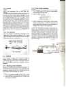
2-3. MOBILE 5 4-4-4. PLL unit (X50-2050-00) 20
2-3-1. Mounting bracket installation 5 4-4-5. Final unit (X45-1470-00) , 20
2-3-2. Power supply connection 5 4-4-6. Filter unit (X51-1340-00) 20
3. OPERATION 6 4-4-7. ~xT5~~~~~~~~~).~.~~.~~.~.~.~~.~~~~.~.~~~, 20
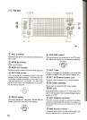
3-1. OPERATING CONTROLS 6 5. MAINTENANCE AND ADJUSTMENT 21
3-1-1. Front panel 6
3-1-2. Rear panel 10 5-1. GENERAL INFORMATION , 21
3-1-3. Top cover ".".'."..'.'."."'.'..'.".'."."'" 11 5-2. SERVICE 21
3-2. RECEIVE 12 5-3. CLEANING 21
3-2-1. Initial setting 12 5-4. IN CASE OF DIFFICULTY 21
3-2-2. CW zero-beat operation 12 5-5. MICROPROCESSOR BACK-UP
3-2-3. Direct keyboard frequency entry 13 LITHIUM BATTERY 22
3-2-4. AM reception 13 5-6. MICROPROCESSOR RESET 22
3-3. TRANSMIT 13 5- 7. ORDERING SPARE PARTS 22
3-3-1. SSB (LSB, USB) mode 13 5-8. ADJUSTMENTS 23
3-3-2. CW mode 14
5 8 1 C I 23( ) S .
t t. b k .
14 --.over remova , a eml-au oma IC rea -In 5 8 2 I I .
23(b) F II . b k .
14 --.nterna views u -automatic rea -In 5 8 3 D..
I d. I I.b t.
243 3 3 FM d 14 --.Iglta ISp ay ca I ra Ion --.mo e 5 8 4 O .
I 1 0 H d . I I t.
24S b d.
bl 15 --.ptlona z ISp ay reso u Ion .u au I e tone 5-8-5. CW zero beat frequency selection ,.. ...24
3-3-4. AM mode 15
5 8 6 S.
d I I 253-4. AUTOMATIC ANTENNA TUNER 15 --.I e tone eve ..: 5-8-7. Beep tone selection 25
3-5. DUAL DIGITAL VFO's 15 5-8-8. Beep tone level 25
3-5-1. Why two VFO's 15 5-8-9. Tuning dial torque.. 26
3-5-2. Split frequency 15 5-8-10. Linear amplifier control 26
(a) A=B switch 15 6. OPTIONAL ACCESSORIES 27
(b) A/B switc.h 15 6-1. CRYSTAL FILTER INSTALLATION 27
(c) SPLIT SWltC~ 15 6-2. VOICE SYNTHESIZER UNIT VS-1
(d) T -F SET switch .'..'.""""""..'..'.'."." 15
3-6. MEMORY 16 INSTALLATION.. 28
6-3. INTERFACE IC KIT IC-10
3-6-1. Memory entry 16
3-6-2. Transferring memory information to the INSTALLATION 29
VFO 16 6-4. OTHER ACCESSORIES 30
3-6-3. Transferring data between memory 7. BLOCK DIAGRAM 33
channels 17 8. SCHEMATIC DIAGRAM... 34
3-6-4. Entering/Transferring data in the split --9. SPECIFICATIONS AND ACCESSORIES 41
frequency channels 3-6-5. Clearing a memory channel 9-1. SPECIFICATIONS 41
3-6-6. Memory recall 9-2. ACCESSORIES 42
3-7. SCAN ' 10. REFERENCE 43
3-7-1. Memory scan 10-1. ANTENNA INSTALLATION 43
3-7-2. Program scan 10-1-1. Fixed station 43
3- 7-3. Scan speed 10-1-2. Mobile 43
3-7-4. Memory channel lockout 10-2. MOBILE OPERATION 44
3-8. AFSK 10-2-1. Installation 44
3-8-1. Reception 10-2-2. Noise reduction 45
3-8-2. Transmit 10-2-3. Battery capacity , 45
3-8-3. AMTOR operation 10-3. RADIO FREQUENCY ALLOCATION 46
3-9. OPERATION WITH A LINEAR AMPLIFIER
.1 /
.17
.17
17
.17
.18
.18
.18
19
.19
.19
.19
.19
2