


10.
REFERENCE
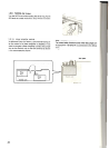
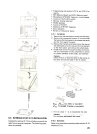
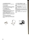
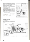
10-1-2. Mobile
(1) Antenna
Use a sturdy mount for the mobile antenna since HF
antennas are larger (and have more wind load) and are
heavier than VHF antennas. A bumper mount is recom-
mended for general use. The ground side of the mount
must be well grounded to the car body, since the body
itself functions as the ground plane for the mobile an-
tenna. (Refer to Fig. 10-4)
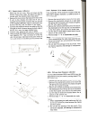
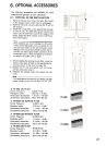
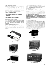
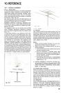
10-1. Antenna installation
10-1-1. Fixed station
For HF fixed-station operation, an antenna specifically
designed for amateur operation is recommended. An-
tenna types include wire antennas, verticals, rotary
beams, and other antenna types. (Fig. 10-1) HF anten-
nas are quite large and must be installed to withstand
strong wind, heavy rain, etc.
Any antenna used with the TS-440S should be of
50-ohm impedance and should be connected using an
appropriate coaxial cable such as RG-8/U.
Impedance matching is important. Impedance mis-
matching will result in a high VSWR and power loss,
or can cause unwanted harmonic radiation and inter-
ference (TVI, BCI).
The impedance match can be checked with an SWR
meter. Generally, satisfactory operation is assured
when the VSWR (Voltage Standing Wave Ratio) is less
than 1.5: 1 .
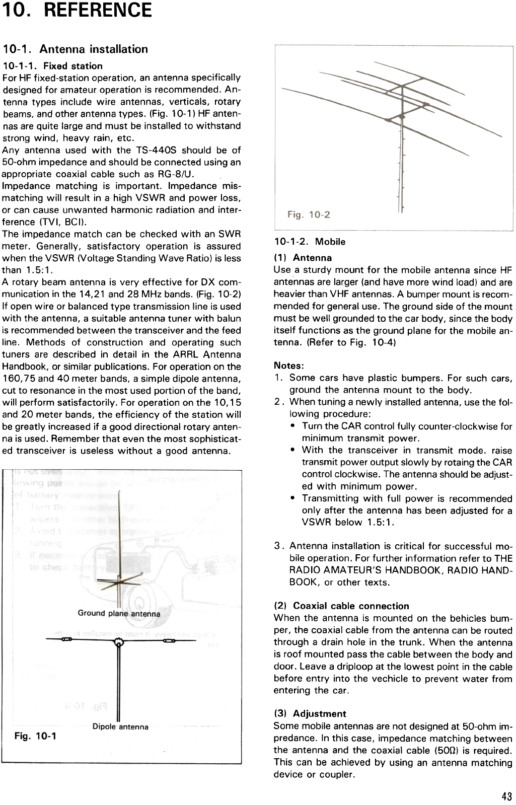
A rotary beam antenna is very effective for OX com-
munication in the 14,21 and 28 MHz bands. (Fig. 10-2)
If open wire or balanced type transmission line is used
with the antenna, a suitable antenna tuner with balun
is recommended between the transceiver and the feed
line. Methods of construction and operating such
tuners are described in detail in the ARRL Antenna
Handbook, or similar publications. For operation on the
160,75 and 40 meter bands, a simple dipole antenna,
cut to resonance in the most used portion of the band,
will perform satisfactorily. For operation on the 10,15
and 20 meter bands, the efficiency of the station will
be greatly increased if a good directional rotary anten-
na is used. Remember that even the most sophisticat-
ed transceiver is useless without a good antenna.
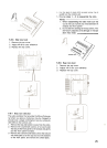
Notes:
1. Some cars have plastic bumpers. For such cars,
ground the antenna mount to the body.
2. When tuning a newly installed antenna, use the fol-
lowing procedure:
.Turn the CAR control fully counter-clockwise for
minimum transmit power.
.With the transceiver in transmit mode. raise
transmit power output slowly by rotaing the CAR
control clockwise. The antenna should be adjust-
ed with minimum power.
.Transmitting with full power is recommended
only after the antenna has been adjusted for a
VSWR below 1.5:1.
3. Antenna installation is critical for successful mo-
bile operation. For further information refer to THE
RADIO AMATEUR'S HANDBOOK, RADIO HAND-
BOOK, or other texts.
Ground plane antenna
(2) Coaxial cable connection
When the antenna is mounted on the behicles bum-
per, the coaxial cable from the antenna can be routed
through a drain hole in the trunk. When the antenna
is roof mounted pass the cable between the body and
door. Leave a driploop at the lowest point in the cable
before entry into the vechicle to prevent water from
entering the car.
Dipole antenna
(3) Adjustment
Some mobile antennas are not designed at 50-ohm im-
predance. In this case, impedance matching between
the antenna and the coaxial cable (500) is required.
This can be achieved by using an antenna matching
device or coupler.
Fig. 10-1
43