


.Subaudible tone
An optional subaudible tone unit TU-8 is available for
installation in the TS-440S for accessing 10 meter FM
repeaters. This tone is activated whenever the
TS-440S is in the SPLIT mode.
3-5-1. Why two VFO's
Occasionally OX stations will utilize an operational
procedure known as split frequency operation. When
the OX station is in this mode he will be transmitting
on one frequency and receiving on another. This is
done in order for the OX station to be able to recog-
nize the calls of stations during pile-ups.
Older transceivers required the use of an external VFO
to allow this split frequency operation. The TS-440S,
thru the use of microprocessor controls, effectively pro-
vides two separate VFOs in the same package. Several
different controls and switches have been provided to
increase the operators convenience when faced with
this type of operation. The use of these controls is dis-
cussed below.
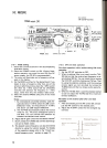
3-3-4. AM mode
1. Set the Meter switch to PWR.
2. Set the MODE key to AM.
3. Place the Standby switch to SEND.
4. Adjust the CAR control so that the meter indicates
25 watts.
5. Place the Meter switch to ALC.
6. Adjust the MIC gain control so that the meter
deflection does not exceed ALC zone on voice
peaks.
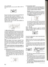
3-5-2. Split frequency
(a) A=B switch
Depressing this switch causes the data contained
in the inactive VFO (the VFO that is not currently
being displayed) to change to the same data con-
tained in the active VFO (the one currently dis-
played). Both the frequency and mode are
changed.
3-4. AUTOMATIC ANTENNA TUNER
(The AT unit AT -440 is required for
this function.)
The automatic antenna tuner operates within the
amateur radio bands from 3.5 thru 29.7 MHz.
1. Ensure that an antenna designed for use within the
band you intend to operate on is properly connect-
ed to the antenna terminal.
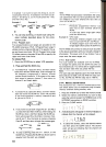
For example: VFO A is set at 7 MHz in LSB, and
VFO B is 21 MHz in USB. VFO A is the active VFO
(show on the display). Depressing the A = B switch
will cause VFO B to change to 7 MHz in LSB.
2. Set the AUTO/THRU switch to the AUTO position,
3. Place the A T TUNE switch to the ON position. The
AT TUNE indicator will light and the tuner will be-
gin tuning. Then the CW mode indicator will light.
(b) A/B switch
Allows selection of the desired active VFO. Each
time this switch is depressed the active VFO will
alternate between VFO A and VFO B.
4. After a short period the ATTUNE indicator will go
OFF and the motors will stop turning.
5. Place the ATTUNE switch to OFF
(c) SPLIT switch
Allows the use of one VFO for transmit, and the
other for receive (Split Frequency operation). For
example: VFO A is the active VFO, and VFO B is
the inactive VFO. Depressing the SPLIT switch will
cause the TS-440S to receive on VFO A and trans-
mit on VFO B. The mode of reception and trans-
mission will follow the mode contained in the
appropriate VFO memory. It is possible to work
cross band, cross mode if desired.
6. Tuning is now completed. You may now carry out
normal communications.
Notes:
1. When the AT TUNE switch is ON and the AT indi-
cator lights but then goes out immediately it is an
indication that the antenna was not that far off
resonance and that tuning has been completed.
2. Normal operation is not possible until the ATTUNE
switch has been turned OFF.
3 .If the motors do not stop turning after approximately
30 seconds, place the AT TUNE switch to OFF, and
then back to ON again. The tuner will attempt to
tune again, and should find a good match. If the
tuner will not stop after several tries it indicates
some problem exists with the antenna system.
Readjust the antenna and feedline before attempt-
ing to tune again.
To avoid confusion during contest, or pile-up oper-
ations we recommend using VFO A for receive and
VFO B for transmit.
(d) T -F SET switch
Depressing this switch will allow you to rapidly set
or check the transmit frequency, during SPLIT
operations, without the need of actually trans-
mitting.
This switch is especially convenient when you are
trying to locate the transmit frequency of the sta-
tion currently in contact with the OX station, since
3-5. DUAL DIGITAL VFO's
Operational convenience can be enhanced thru the use
of both VFO A and VFO B.
15