


13
PROCEDURE 4ADJUSTING THE INFINITY BACK
A
D
J
U
S
T
I
N
G
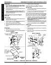
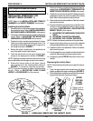
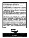
6. Slide one (1) lateral support to the desired location.
7. Visually inspect the adjustment slot to find proper lo-
cation for the curved washer.
8. Remove one (1) mounting screw, tooth lock washer
and curved washer.
9. Hold the mounting screw with the threads UP.
10. Position the tooth lock washer on the mounting screw.
11. Position the curved washer on the mounting screw
so that the bent portion is toward the threaded end of
the mounting screw.
12. Install the mounting screw with washers through the
toothed adjustment slot and into the lateral support.
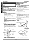
13. Torque the mounting screw to 45-50 in./lbs., ensur-
ing the curved washer is seated properly in the
toothed adjustment slot shown in FIGURE 5.
14. Repeat STEPS 8-13 for the remaining mounting
screw on the lateral support.
15. Repeat STEPS 6-14 for the remaining lateral supports.
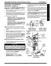
Adjusting the Height
NOTE: Both sets of lateral supports can be adjusted to
three (3) different height positions.
1. Remove the two (2) mounting screws, tooth lock wash-
ers and curved washers securing the lateral support to
the Infinity Back.
2. Hold one (1) mounting screw with the threads UP.
3. Position the tooth lock washer on the mounting screw.
4. Position the curved washer on the mounting screw so
that the bent portion is TOWARD the head of the mount-
ing screw as shown in DETAIL "A" of FIGURE 5.
5. Repeat STEPS 2-4 for the remaining mounting screw
and washers.
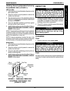
6. Position the lateral support in the upper, middle or lower
position, aligning the mounting holes of the support with
the adjustment slot in the Infinity Back as shown in DE-
TAIL "B" of FIGURE 5.
NOTE: The grooves next to the mounting holes in the
lateral support are provided to align lateral supports on
either side of the Infinity Back. Look through the toothed
adjustment slot to see which mounting hole has been used
and use the corresponding mounting hole on the oppo-
site lateral support if desired.
7. Loosely install the two (2) mounting screws and washers
to secure the supports to the back as shown in DETAIL
"B" of FIGURE 5.
NOTE: The curved washer should be facing away from
the Infinity Back for ease of adjustment.
8. Adjust the width of the lateral supports. Refer to ADJUST-
ING THE WIDTH in this procedure of the manual.
Lateral Thoracic
Support
Hip
Guides
Mounting
Screws
Washers
LOOSEN
Mounting
Screws and
SLIDE Lateral
Pads
Toothed Adjustment Slot
FIGURE 5 - ADJUSTING THE LATERAL
SUPPORTS
UPPER
Back
Panel
LOWER
Back Panel
Lateral Thoracic Support
Hip Guide
Mounting
Screw
Washer
Curved Washer
Toothed Adjustment
Slot
Back
Panel
Back Panel
DETAIL "B"
Grooves
Grooves
Curved
Washer
Toothed Adjustment Slot
Tooth Lock Washer
Mounting
Screws
DETAIL "A"