


12
ADJUSTING THE INFINITY BACKPROCEDURE 4
A
D
J
U
S
T
I
N
G
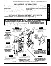
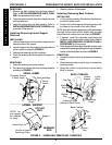
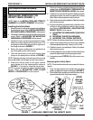
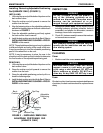
Converting Fixed Angle Hinges to Dynamic
Flex Hinges (FIGURE 3)
1. Remove the four (4) short mounting screws securing the
hinge to the back panels.
NOTE: Save the short mounting screws for future conversion
to fixed angle hinges.
2. Position the elastomers, spacers and washers as shown
in FIGURE 3.
NOTE: Ensure all mounting holes are aligned.
3. Align the hinge with the mounting holes on each back panel.
4. Install the four (4) long mounting screws. Torque to 45-50
in./lbs.
5. Adjust the lateral supports. Refer to ADJUSTING THE
LATERAL SUPPORTS in this procedure of the manual.
Elastomer
Spacer
Washer
Mounting Screws
Hinge
FIGURE 3 - ADJUSTING THE HINGE
(DUALFLEX ONLY) - CONVERTING HINGES
Back
Panel
Mounting
Holes
Hinge Mounting
Hole
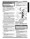
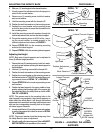
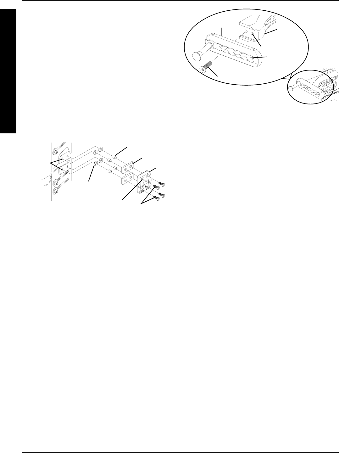
ADJUSTING THE DEPTH
HARDWARE (FIGURE 4)
NOTE: Refer to the INSTALLATION AND STABILITY
WARNINGS in the SAFETY SUMMARY of this manual.
1. Ensure all cushions have been installed on the Infinity
Back. Refer to INSTALLING/REMOVING CUSHIONS
in PROCEDURE 2 of this manual.
2. Hold the Infinity Back up to the wheelchair.
3. Visually inspect the Infinity Back and the wheelchair
to determine the desired depth.
4. Loosen the mounting screw in the depth bracket.
5. Slide the depth bracket until the mounting screw is
positioned in the desired adjustment hole.
NOTE: The width bracket has two (2) mounting holes. It
may be necessary to move the mounting screw to the
other hole to achieve the desired depth.
6. Torque mounting screw to 45-50 in./lbs. to secure depth
bracket to width bracket.
7. Perform one (1) of the following:
DUALFLEX - Adjust the hinge and/or angle of the back,
if present. Refer to ADJUSTING THE HINGE/ANGLE
in this procedure of the manual.
UNIBACK - Proceed to ADJUSTING THE LATERAL
SUPPORTS in this procedure of the manual.
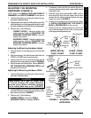
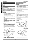
ADJUSTING THE LATERAL
SUPPORTS (FIGURE 5)
NOTE: Refer to the INSTALLATION AND STABILITY
WARNINGS in the SAFETY SUMMARY of this manual.
NOTE: Lateral supports include the lateral thoracic sup-
ports and the pelvic stabilizers.
Adjusting the Width
1. Visually inspect the orientation of one (1) curved
washer on one (1) lateral support.
2. Perform one (1) of the following:
A. Curved washer oriented as shown in DETAIL
"A" of FIGURE 5 - Perform the following steps:
a. Loosen, but do not remove the mounting
screw.
b. Proceed to STEP 3.
B. Curved washer oriented as shown in DETAIL
"B" of FIGURE 5 - Perform the following steps:
a. Hold the mounting screw with the threads
UP.
b. Position the tooth lock washer on the
mounting screw.
c. Position the curved washer on the mount-
ing screw so that the bent portion is TO-
WARD the head of the mounting screw
as shown in DETAIL "A" of FIGURE 5.
d. Loosely install the mounting screw with
washers through the adjustment slot and
into the lateral support.
3. Repeat STEPS 1-2 for the other mounting screw
on the same lateral support.
4. Repeat STEPS 1-3 for the remaining lateral sup-
ports which need adjustment.
5. Position the user in the wheelchair.
Depth
Bracket
Mounting Screw
Mounting Hole
Adjustment
Hole
Width
Bracket
FIGURE 4 - ADJUSTING THE DEPTH
HARDWARE