


11
ADJUSTING THE INFINITY BACK PROCEDURE 4
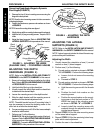
ADJUSTING THE HINGE/ANGLE
(DUALFLEX ONLY)
NOTE: Refer to the INSTALLATION AND STABILITY
WARNINGS in the SAFETY SUMMARY of this manual.
NOTE: The following procedures apply to the DualFlex
ONLY. If installing/adjusting a UniBack proceed to ADJUST-
ING THE LATERAL PADS in this procedure of the manual.
NOTE: Both hinges should be adjusted to have fixed
angles OR both hinges should be adjusted to have Dy-
namic Flex angles.
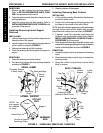
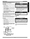
Adjusting the Angle (FIGURE 2)
1. Loosen the adjustment screws on both hinges.
2. Grasp and hold the top of the upper back panel and
bottom of the lower back panel.
3. Push or pull to adjust the angle of the back to the
desired angle.
4. Torque the adjustment screws on both hinges to 45-
50 in./lbs.
5. Install the Infinity Back onto the wheelchair. Refer
to INSTALLING/REMOVING THE INFINITY
BACK in PROCEDURE 3 of the manual.
6. Adjust the lateral supports. Refer to ADJUSTING THE
LATERAL SUPPORTS in this procedure of the manual.
UPPER
Back Panel
LOWER
Back Panel
Hinge
Adjustment
Screw
FIGURE 2 - ADJUSTING THE HINGE
(DUALFLEX ONLY) - ADJUSTING THE ANGLE
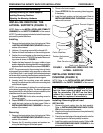
WARNING
For proper installation of the Infinity Back
and to reduce the risk of pressure sores,
the adjustment procedures below MUST be
performed in the following order:
1. Adjusting the Mounting Hardware
2. Adjusting the Hinge/Angle
(DUALFLEX ONLY)
3. Adjusting the Depth Hardware
4. Adjusting the Lateral Pads
NOTE: To simplify the adjustment procedures, remove
the back from the wheelchair. Refer to INSTALLING/
REMOVING THE INFINITY BACK in PROCEDURE 3
of this manual.
NOTE: After performing each procedure, reinstall the back,
place the user in the wheelchair and inspect to ensure the
correct adjustments have been made for user comfort. If nec-
essary, repeat the procedure until the user is comfortable.
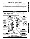
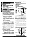
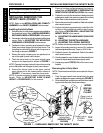
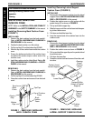
ADJUSTING CANE CLAMP HEIGHT
(FIGURE 1)
NOTE: Refer to the INSTALLATION AND STABILITY
WARNINGS in the SAFETY SUMMARY of this manual.
1. Loosen the mounting screw on the cane clamp.
2. Slide the cane clamp and if necessary, the insert inside
the cane clamp, up or down to the desired position.
3. Torque the mounting screw to 45-50 in./lbs.
4. Repeat STEPS 1-3 for the remaining clamps, if
necessary.
This Procedure includes the following:
Adjusting Cane Clamp Height
Adjusting the Hinge/Angle (DualFlex ONLY)
Adjusting the Depth Hardware
Adjusting the Lateral Supports
Back Cane
Mounting Screw
Upper (Swivel)
Cane Clamp
Lower (Fixed)
Cane Clamp
Mounting Screw
Adjust Cane
Clamps UP
or DOWN
FIGURE 1 - ADJUSTING CANE CLAMP
HEIGHT
A
D
J
U
S
T
I
N
G
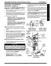
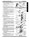
Converting Dynamic Flex Hinges to Fixed
Angle Hinges (FIGURE 3)
1. Remove the four (4) long mounting screws securing
the hinge to the back panels.
2. Remove the elastomers, spacers and washers.
NOTE: Save the long mounting screws, elastomers, spac-
ers and washers for future conversion to Dynamic Flex.
3. Position the hinge on the back, aligning the hinge
mounting holes with the back panel mounting holes
as shown in FIGURE 3.
4. Install the four (4) short mounting screws. Torque to 45-
50 in./lbs.
5. Repeat STEPS 1-4 for opposite hinge.
6. Adjust the angle of the hinge. Refer to ADJUSTING
THE ANGLE in this procedure of the manual.
7. Adjust the lateral supports. Refer to ADJUSTING THE
LATERAL SUPPORTS in this procedure of the manual.