


10
INSTALLING/REMOVING THE INFINITY BACK
INSTALLING/REMOVING THE
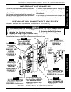
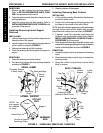
INFINITY BACK (FIGURE 1)
NOTE: Refer to the INSTALLATION AND STABILITY
WARNINGS in the SAFETY SUMMARY of this manual.
Installing the Infinity Back
1. Ensure the four (4) cane clamps are securely installed on
the wheelchair frame. Refer to INSTALLING/REMOV-
ING CANE CLAMPS in PROCEDURE 1 of this manual.
2. If necessary, adjust the mounting hardware to fit the back
canes. Refer to ADJUSTING THE MOUNTING
HARDWARE in PROCEDURE 2 of this manual.
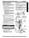
3. Position the lower mounting pins between the lower
(fixed) cane clamp flanges and the back canes. The
mounting pins should be aligned with the groove in
the flange as shown in FIGURE 1.
4. Ensure the upper mounting pins are positioned on
top of the upper (swivel) cane clamps.
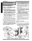
5. Twist the clamp locks on the upper (swivel) cane
clamps to the open position shown in FIGURE 1.
NOTE: Opening the clamp locks will cause the mounting
pins to slide down into the upper (swivel) cane clamps.
6. Ensure the clamps locks on the upper (swivel)
cane clamps are in the closed position shown in
FIGURE 1. If necessary, close the clamp locks.
NOTE: It may be necessary to adjust the cane clamp
height. Refer to ADJUSTING CANE CLAMP
HEIGHT in PROCEDURE 4 of this manual.
7. Ensure all cushions and lateral supports have been in-
stalled. Refer to PROCEDURE 2 - PREPARING THE
INFINITY BACK FOR INSTALLATION in this manual.
8. Position the user into the wheelchair to determine which
adjustments need to be made to properly fit the Infinity
Back. Refer to the wheelchair owner's manual.
9. Remove the user from the wheelchair. Refer to the wheel-
chair owner's manual.
10. Perform the following procedures to adjust the Infin-
ity Back to fit the wheelchair and the user if neces-
sary. Refer to PROCEDURE 4 - ADJUSTING THE
INFINITY BACK in this manual.
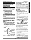
A. ADJUSTING THE HINGE/ANGLE (DUALFLEX
ONLY)
B. ADJUSTING THE DEPTH HARDWARE
C. ADJUSTING THE LATERAL SUPPORTS
NOTE: Perform the above procedures in the order listed.
11. Inspect all mounting screws to ensure ALL hardware
has been tightened securely. Torque to 45-50 in./lbs.
12. Position the user in the wheelchair. Refer to the wheel-
chair owner's manual.
13. Visually inspect the user, the back and the wheelchair to
ensure all adjustments have been properly made.
14. If necessary, repeat STEPS 9-13 until the user is com-
fortable.
Removing the Infinity Back
NOTE: The wheelchair should be unoccupied for this pro-
cedure.
1. Twist the upper (swivel) cane clamp locks in the open
position to release the upper mounting pins (FIGURE 1).
2. Lift the Infinity Back upwards to remove the lower mount-
ing pins from the lower (fixed) cane clamps.
This Procedure includes the following:
Installing/Removing the Infinity Back
PROCEDURE 3
I
N
S
T
A
L
L
I
N
G
/
R
E
M
O
V
I
N
G
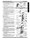
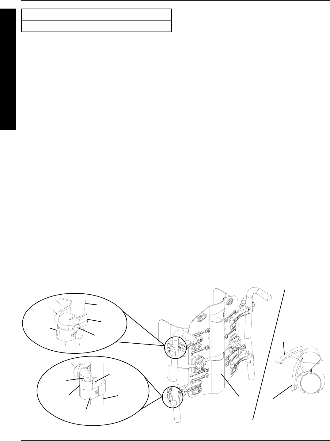
FIGURE 1 - INSTALLING/REMOVING THE INFINITY BACK
Installed DualFlex
Infinity Back
(UNIBACK NOT
SHOWN)
Upper
(Swivel)
Cane
Clamp
Mounting
Pin
Back
Cane
Clamp
Lock
UPPER
(SWIVEL)
CANE
CLAMP
Clamp Lock in
CLOSED
Position
Clamp Lock in
OPEN Position
TOP
VIEW
Lower (Fixed)
Cane Clamp
Mounting
Pin
Back
Cane
Flange
Groove