


Temperature is generally sensed at the tip of the probe. To get an accurate tem
-
perature measurement the probe sheath should be well immersed, with ade
-
quate depth and fit, into the medium to be measured.
CAUTION: Probes are fragile devices that can be easily damaged by me
-
chanical shock, overheating, and absorption of moisture or fluids in the
wires or hub. Damage may not be visibly apparent but nevertheless can
cause drift, instability, and loss of accuracy. Observe the following pre
-
cautions:
Do not allow probes to be dropped, struck, bent, or stressed.
Do not overheat probes beyond their recommended temperature range.
Do not allow any part of the probe other than the sheath to be immersed in
fluid.
Do not allow the probe hub or wires to be exposed to excessive temperatures.
Keep the probe wires clean and away from fluids.
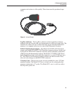
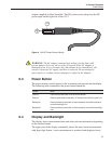
6.6 INFO-CON Connector
The probe connects to the top of the 1522 using a Hart INFO-CON connector
(see Figure 3 on page 21). The probe connector fits snugly and locks into place
when it is fully inserted. The connector includes a memory device that stores
the unique characteristics of the probe, allowing the instrument to measure tem-
perature accurately. Generally, the probe is purchased with the connector at-
tached and programmed by the factory. Connectors can be purchased separately
and installed onto probes by the user. The INFO-CON can be programmed di-
rectly from the 1522 or from a PC with the optional Model 2372 accessory and
9972 software.
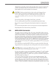
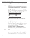
If it is necessary to install the INFO-CON onto a probe in the field, follow the
diagram below for connecting the wires of the probe to the connector terminals.
CAUTION: Before opening the INFO-CON case, be sure to be grounded
with an ESD strap to avoid damaging the memory chip.
For four-wire probes, one pair of wires attaches to terminals C1 and P1 and the
other pair attaches to terminals C2 and P2. (C1 and C2 source current and P1
and P2 sense the potential.) If a shield wire is present, it should be connected to
the GND terminal (see Figure 7).
A two-wire or three-wire probe can also be used with the instrument. The
two-wire probe is connected by one wire to the C1 and P1 shorted terminals
and the other wire to the C2 and P2 shorted terminals. Recognize that accuracy
may be significantly degraded using a two-wire connection because of wire re
-
sistance. A three-wire probe is connected by attaching the common wires to the
29
6 General Operation
INFO-CON Connector