


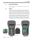

5.3 Back View
See Figure 5 on page 25.
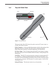
Stand - The stand at the back of the 1522 can be flipped down to prop up the
instrument for better viewing.
Battery Compartment - Behind the stand is the compartment that contains the
battery pack. The battery pack can be accessed if necessary by opening the bat
-
tery cover with a small Philips screwdriver (see Section 6.1).
Serial Number Label - Also behind the stand is the serial number label that
uniquely identifies the instrument.
5.4 Internal Features
The significant components inside the 1522 are described here.
Battery - The 1522 has an internal rechargeable battery pack that can be re
-
charged by the AC adapter without removing the battery. It can be used and re-
charged many times. If necessary, it can be easily removed and replaced (see
Section 6.1).
Micro-controller - The 1522 uses a micro-controller to control all its func-
tions. The micro-controller manages the measurement process, retrieves mea-
surement data from the analog-to-digital converter (ADC), places
measurements and other information on the display, senses button actions,
reads battery status information from the power control circuit, and handles
communications through the serial port.
Power Control Circuit - The power control circuit manages the electrical
power that drives all the circuits. It handles switching between the two sources
of power (DC input and battery pack), regulates voltages, monitors the state of
battery charge, and manages battery charging.
Analog-to-Digital Converter and Measurement Circuit - The ADC takes an
analog signal produced by the probe and converts it to a digital value that can
be read by the micro-controller. The ADC used in the 1522 was selected for its
excellent resolution, linearity, and stability. The measurement circuit built
around the ADC was carefully designed for accuracy and stability to match the
ADC. The measurement circuit allows complete rejection of probe wire resis
-
tance effects that would otherwise seriously limit accuracy. Offsets from
sources such as thermoelectric EMF are also completely rejected. This is done
using a current reversal technique with the probe current alternating at a rate of
one cycle per second. Self-heating is minimized by using low sensing currents.
For PRTs the current is only 0.5 mA. For thermistors the current is only 0.005
mA.
1522 Handheld Thermometer Readout
User’s Guide
20