


second. The display unit associated with the measurement is shown in smaller
type to the right of the measurement. The possible display units are degrees
Celsius (C), resistance in ohms (Ω), degrees Fahrenheit (F), Kelvin (K), and
degrees Rankine (R). The display units can be easily changed accessing the
Units mode (see Section 7.6).
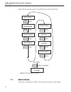
The lower part of the display has various functions depending on the selected
mode. It has smaller alphanumeric characters. It can be used to display mini
-
mum and maximum measurements, delta(x) measurements, or measurements
stored in memory. It is also used to view and set various operating parameters.
The mode is easily changed using the MODE button. (See details on the vari
-
ous modes beginning with Section 7.)
The display has a backlight that can be switched on for better viewing in dim
light. The backlight is switched on and off by pressing and holding the power
button for three seconds (see Section 6.3 above). Note: The battery discharges
more quickly when the backlight is used.
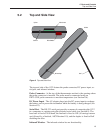
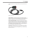
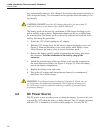
6.5 Probe
The probe is used to sense temperature and attaches to the 1522 using a Hart
INFO-CON probe connector that plugs into the top of the instrument. The
probe connector must be properly programmed with the correct charac-
teristics of the probe for measurements to be accurate (see Section 6.6).
The 1522 can be used with various types of PRT and thermistor probes:
• ITS-90 calibrated 25Ω or 100Ω PRT
• IEC-751 or DIN-43760 PRT (RTD)
•
Callendar-Van Dusen calibrated 100Ω PRT
•
YSI-400 series or equivalent 2252Ω thermistor
•
Steinhart-Hart thermistor polynomial; nominal R(25°C) 2kΩ to 100kΩ
See Section 7.9.8 for details on the various probe types and their programming.
The 1522 cannot be used with thermocouples.
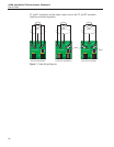
The 1522 can be used with probes having two, three, or four wires. Three-wire
probes allow partial compensation for wire resistance. The 1522 measures
three-wire probes using the following sequence. It measures the sensor resis
-
tance, including the lead resistance in C2. The 1522 then directly measures the
resistance in the C1 lead of the sensor and subtracts the measured C1 lead resis
-
tance from the measured sensor resistance (including the C2 lead resistance) to
obtain the sensor resistance used to calculate temperature. Note: This sequence
assumes that the lead resistance of C1 and C2 are equal. If C1 and C2 each
have a different resistance value, there will be an error in the calculated sensor
resistance equal to this difference. Four-wire probes allow complete rejection of
wire resistance and should be used when the best accuracy is desired. The 1522
wire setting must be set to match the actual number of wires of the probe (see
Section 7.9.14).
1522 Handheld Thermometer Readout
User’s Guide
28