


Quick Start Guide
9
February 2015
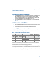
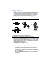
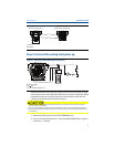
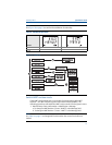
Figure 5. Transmitter Electronics Board
A. Alarm
B. Security
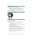
Step 4: Connect the wiring and power up
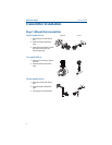
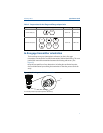
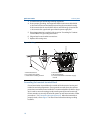
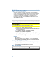
Figure 6. Transmitter Wiring Diagrams (4–20 mA)
A. 24 Vdc supply
B. R
L
≥ 250
C. Current Meter (Optional)
Shielded twisted pair cable should be used for best results. Use 24 AWG or larger
wire that does not exceed 5,000 feet (1500 meters) in length. If applicable, install
wiring with a drip loop. Arrange the drip loop so the bottom is lower than the
conduit connections and the transmitter housing.
Use the following steps to wire the transmitter:
1. Remove the housing cover on the FIELD TERMINALS side.
2. Connect the positive lead to the “+” terminal (PWR/COMM) and the negative
lead to the “–” terminal.
Installation of the transient protection terminal block does not provide transient protection unless the
3051 case is properly grounded.
Do not run signal wiring in conduit or open trays with power wiring, or near heavy electrical equipment.
Do not connect the powered signal wiring to the test terminals. Power could damage the test diode in the
terminal block.
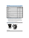
A
B
Without LCD display
With LCD or LOI display
A
B
C