


February 2015
8
Quick Start Guide
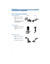
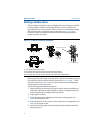
Step 2: Consider housing rotation
To improve field access to wiring or to better view the optional LCD display:
1. Loosen the housing rotation set screw using a 5/64-in. hex wrench.
2. Turn the housing left or right maximum up to 180° from its original position
(1)
.
Please note that over rotating can damage the transmitter.
3. Re-tighten the housing rotation set screw to no more than 7 in-lbs when
desired location is reached.
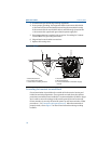
Figure 4. Transmitter Housing Set Screw
A. Housing rotation set screw (5/64-in.)
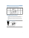
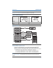
Step 3: Set the switches
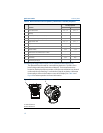
Set Alarm and Security switch configuration before installation as shown in
Figure 5.
The Alarm switch sets the analog output alarm to high or low.
- Default alarm is high.
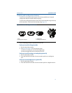
The Security switch allows (unlocked symbol) or prevents (locked symbol) any
configuration of the transmitter.
- Default security is off (unlocked symbol).
Use the following procedure to change the switch configuration:
1. If the transmitter is installed, secure the loop, and remove power.
2. Remove the housing cover opposite the field terminal side. Do not remove the
instrument cover in explosive atmospheres when the circuit is live.
3. Slide the security and alarm switches into the preferred position using a small
screwdriver.
4. Reattach the transmitter cover. The cover must be fully engaged to comply
with explosion-proof requirements.
1. 3051C original position aligns with “H” side; 3051T original position is the opposite side of bracket holes.
A