


Instruction Bulletin
106-300NE Rev. 3.4
May 2000
ii Rosemount Analytical Inc. A Division of Emerson Process Management
World Class 3000
LIST OF ILLUSTRATIONS
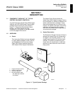
Figure 1-1. Typical System Package ....................................................................................... 1-1
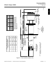
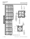
Figure 1-2. Typical System Installation .................................................................................... 1-3
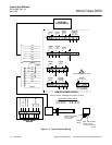
Figure 1-3. Typical System Wiring ........................................................................................... 1-4
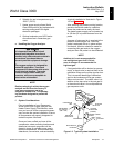
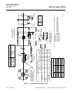
Figure 2-1. Probe Installation ................................................................................................... 2-2
Figure 2-2. Orienting the Optional Vee Deflector ..................................................................... 2-7
Figure 2-3. Outline of Heater Power Supply ............................................................................ 2-7
Figure 2-4. Electrical Installation of Heater Power Supply....................................................... 2-8
Figure 2-5. Heater Power Supply Wiring Connections ............................................................ 2-9
Figure 2-6. Jumper Selection Label ....................................................................................... 2-10
Figure 2-7. Jumpers on HPS Mother Board........................................................................... 2-11
Figure 3-1. Temperature Controller Card Calibration Points ................................................... 3-1
Figure 3-2. Main PCB (Model 218A) EPROM Replacement ................................................... 3-2
Figure 3-3. Main PCB (Model TC200) EPROM Replacement ................................................. 3-3
Figure 3-4. Main PCB (Model 132) EPROM Replacement...................................................... 3-4