


Instruction Bulletin
106-300NE Rev. 3.4
May 2000
Rosemount Analytical Inc. A Division of Emerson Process Management Setup 3-1
World Class 3000
SECTION 3
SETUP
3-1 OVERVIEW
This section covers the setup procedures for the
World Class 3000 Oxygen Analyzer with HPS
3000 Heater Power Supply Field Module. Since
this equipment may be used with a number of
different electronics packages, this section has
been divided into three parts: Models 218, 225,
and 132 (Analog) Electronics, Model 218A,
Electronics, and Model TC200 Electronics. Each
of the three parts contain setup information ap-
plicable to that electronics package.
Install all protective equipment covers
and safety ground leads after setup.
Failure to replace covers and ground
leads could result in serious injury or
death.
Models 218, 225, and 132 (Analog)
Electronics refer to paragraph 3-2.
Model 218A Electronics
refer to paragraph 3-3.
MODEL TC200 Electronics
refer to paragraph 3-4.
Model 132 Digital Electronics
refer to paragraph 3-5.
3-2 MODELS 218, 225, AND 132 (ANALOG)
ELECTRONICS SETUP
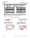
Before beginning operation, it is important that
the probe heater set point of the existing elec-
tronics be changed to support the World Class
3000 probe. The set point adjustment procedure
required for Models 218, 225, and 132 analog
electronics is as follows:
a. Open electronics enclosure.
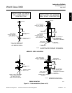
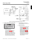
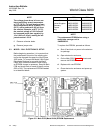
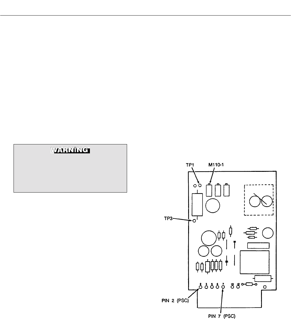
b. On temperature controller card, Figure 3-1,
connect jumper wire from TP3 to either Pin
2 or Pin 7.
c. Set voltmeter to read DC millivolts (MV).
d. Attach voltmeter with positive (+) lead on
TP1 and negative (-) on either Pin 2 or 7.
e. Adjust potentiometer M110-1 to read -322.3
millivolts nominal.
Figure 3-1. Temperature Controller Card
Calibration Points
3