


Instruction Bulletin
106-300NE Rev. 3.4
May 2000
Rosemount Analytical Inc. A Division of Emerson Process Management Installation 2-9
World Class 3000
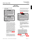
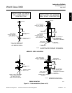
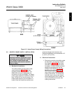
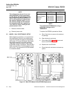
Figure 2-5. Heater Power Supply Wiring Connections
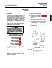
2-2 HEATER POWER SUPPLY INSTALLATION
Install all protective equipment covers
and safety ground leads after installa-
tion. Failure to install covers and
ground leads could result in serious
injury or death.
a. Mechanical Installation
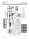
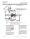
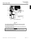
The outline drawing of the heater power
supply enclosure, Figure 2-3, shows
mounting centers and clearances. The
NEMA 4X enclosure is designed to be
mounted on a wall or bulkhead. The heater
power supply should be installed no further
than 150 feet (45 m) from the probe. The
heater power supply must be located in a
location free from significant ambient tem-
perature changes and electrical noise.
Ambient temperature must be between -20°
to 140°F (-30° to 60°C).
b. Electrical Connections
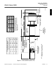
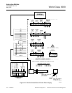
1. Electrical connections should be made
as described in the electrical installa-
tion diagram, Figure 2-4. The wiring
terminals are divided into two layers;
the bottom (FROM PROBE) terminals
should be connected first, the top
(FROM ELECTRONICS) terminals
should be connected (Figure 2-5).
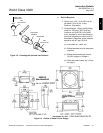
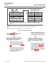
Each terminal strip has a protective
cover which must be removed when
making connections. To remove the
terminal covers, remove two slotted
screws holding the cover in place. Al-
ways reinstall terminal covers after
making connections.
2