


Instruction Bulletin
106-300NE Rev. 3.4
May 2000
Rosemount Analytical Inc. A Division of Emerson Process Management Installation 2-1
World Class 3000
SECTION 2
INSTALLATION
2-1 OXYGEN ANALYZER (PROBE)
INSTALLATION
Before starting to install this equip-
ment, read the "Safety instructions for
the wiring and installation of this ap-
paratus" at the front of this Instruction
Bulletin. Failure to follow the safety
instructions could result in serious
injury or death.
Install all protective equipment covers
and safety ground leads after installa-
tion. Failure to install covers and
ground leads could result in serious
injury or death.
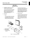
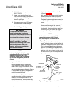
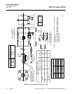
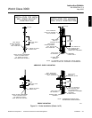
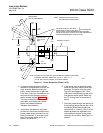
a. Selecting Location
1. The location of the probe in the stack
or flue is most important for maximum
accuracy in the oxygen analyzing pro-
cess. The probe must be positioned so
that the gas it measures is representa-
tive of the process. Best results are
normally obtained if the probe is posi-
tioned near the center of the duct (40
to 60% insertion). A point too near the
edge or wall of the duct may not pro-
vide a representative sample because
of the possibility of gas stratification. In
addition, the sensing point should be
selected so that the process gas tem-
perature falls within a range of 50° to
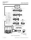
1300°F (10° to 704°C). Figure 2-1 pro-
vides mechanical installation
references.
2. Check the flue or stack for holes and
air leakage. The presence of this con-
dition will substantially affect the accu-
racy of the oxygen reading. Therefore,
either make necessary repairs or install
the probe upstream of any leakage.
3. Ensure that the area is clear of ob-
structions internal and external that will
interfere with installation. Allow ade-
quate clearance for removal of probe
(Figure 2-1).
Do not allow the temperature of the
probe junction box to exceed 300°
°°
°F
(149°
°°
°C) or damage to the unit may re-
sult. If the probe junction box tempera-
ture exceeds 300°
°°
°F (149°
°°
°C), the user
must fabricate a heat shield or provide
adequate cooling air to the probe junc-
tion box.
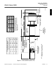
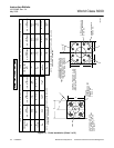
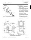
b. Mechanical Installation
1. Ensure that all components are avail-
able for installation of the probe.
Ensure that the system cable is the re-
quired length. If applicable, check the
ceramic filter to ensure that it is not
damaged.
2. The probe may be installed intact as it
is received. It is recommended that you
disassemble the adapter plate for each
installation.
NOTE
An abrasive shield is recommended
for high velocity particulate in the flue
stream (such as those in pulverized
coal kilns and recovery boilers). Verti-
cal and horizontal brace clamps are
provided for 9 ft and 12 ft (2.75 m and
3.66 m) probes to provide mechanical
support of the probe. Refer to Figure
2-1, Sheet 5.
3. Weld or bolt adapter plate (Figure 2-1)
onto the duct.
2