


support.dell.com Service Information for Technicians 7-21
3. Remove all cooling fans from the back of the storage system (see "Replacing a
Cooling Fan," found earlier in this chapter).
4. Remove the enclosure module(s), hereafter called a module (see "Replacing an
Enclosure Module," found earlier in this chapter).
5. Remove the component mounting bracket (see "Removing and Reinstalling the
Component Mounting Bracket," found earlier in this chapter).
6. Remove the dual-bus split backplane module (see "Removing the Dual-Bus Split
Backplane Module," found earlier in this chapter).
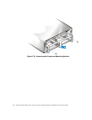
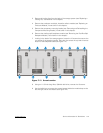
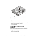
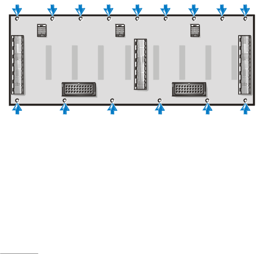
7. Looking in the back of the storage system, locate the 15 screws that secure the
two halves of the chassis together. There are nine across the top and six across
bottom of the backplane board (see Figure 7-11).
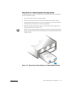
)LJXUH6FUHZ/RFDWLRQ
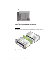
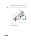
8. Using an 11 1/2-inch–long Allen, 5/64-inch ball driver, remove the 15 screws.
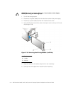
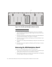
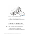
9. Use the ball driver to remove the screws located inside the module bays on the
left and right side of the chassis (see Figure 7-12).