


Page 7
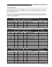
User Inputs/Outputs
The weight sensor controller has five required user inputs and five optional user outputs. At least four user
inputs are required to be connected in order for the ramp to function, whereas none of the user outputs
must be connected (optional).
Below is a list of the user inputs and outputs, including the designated connector pin number, wire color,
and description. Please note the optional user outputs have maximum limitations as specified in the
“Restrictions” column below.
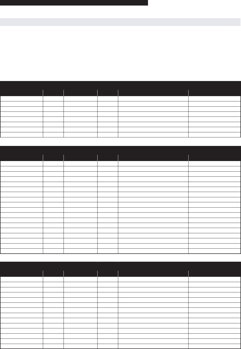
Controller to Vehicle Connections (929.505-3 Amp Connector)
Function Pin # Wire Color LED Description Restrictions
Input (Pulse) 1 Black LD10 Ramp Enable Required
Input (Pulse) 2 Brown LD11 Ramp Operate Required
Input (Continuous) 3 Red LD12 Door Full Open Required
Input (Pulse) 4 Orange Reset Controller Optional
Power Supply 5 Yellow +24 V Supply 10 A Time Delay Fuse
Power Ground 6 Blue Ground Required
Input (Pulse) 7 Violet/Yellow LD13 Close All Doors Required
Input 8 Violet/Green LD14 Extra Optional
Ramp to Controller Connections (T1730-S14 Thomas & Betts Connector)
Function Pin # Wire Color LED Description Restrictions
Input 1 Yellow/Red LD6 Pressure Mat Return
Power 2 Green/Black Ramp + 24 V
Power 3 Orange/Black Ramp Ground
Input 4 Orange LD1 Ramp full out sensor
Input 5 Green/Black LD2 Ramp full in sensor
Output 6 Red/White LD29 Drive Motor +
Output 7 Yellow LD30 Drive Motor -
Input 8 Blue LD3 Ramp full up sensor
Input 9 Yellow LD4 Ramp full down sensor
Not Used 10
Not Used 11
Input 12 Brown LD5 Ramp manual release sensor
Output 13 Black/Red LD27 Elevate motor +
Output 14 Orange/Red LD28 Elevate motor -
All Connections on this Connector Optional (929.505-6 Amp Connector)
Function Pin # Wire Color LED Description Restrictions
Input 1 Green Relay Power (+24 V) 10 A Time Delay Fuse
Output 2 Purple N.C. Ramp Enabled
Output 3 Grey LD17 N.O. Ramp Enabled Required
Output 4 White N.C. Open Door
Output 5 Black/White LD18 N.O. Open Door Required
Output 6 Black N.C. Ramp Malfunction
Output 7 Red/White LD19 N.O. Ramp Malfunction
Output 8 Orange/Red N.C. Clear Signal
Output 9 Yellow/White LD20 N.O. Clear Signal Required
Output 10 Blue/White N.C. Manual Release Unlocked
Output 11 Green/White LD21 N.O. Manual Release Unlocked
Output 12 Red/Black LD22 N.O. Ramp alarm
Power Ground 13 Gray/Pink Ramp alarm ground
Not Used 14
Not Used 15
Not Used 16
Not Used 17
Not Used 18
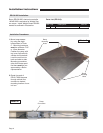
Installation Instructions