


Page 10
Self-Locking Release Pin
The RA200 has the capability of
being manually operated (me-
chanical or electrical methods). If
you experience power or equip-
ment failure, refer to the step-
by-step instructions to manually
operate the ramp. Always use ex-
treme caution when operating the
ramp manually. Read all Manual
Operating Instructions carefully
and thoroughly prior to perform-
ing manual operating procedures.
Follow all Ramp Operation Safety
Precautions at all times.
Mechanical Method
Cable-Activated Manual Re-
lease System: A cable activated
manual release system disen-
gages (unlocks) the carriage as-
sembly drive chains to allow the
platform assembly to be manually
extended or retracted as required.
A T-handle is provided on the
release cable for activation of the
manual release system (details
follow).
After manually extending or
retracting the platform assembly,
it is extremely important that the
cable-activated manual release
is positively reengaged to secure
(lock) the platform assembly
before loading a passenger or
continuing vehicle use (details
provided). Failure to reengage
and secure the platform may
result in unintended ramp
movement, which may result
in serious bodily injury and/or
property damage.
Manual Release System Secu-
rity Sensor: A proximity sensor
detects when the cable-activated
manual release system is disen-
gaged (unlocked) and provides a
ground (-) "unlocked" signal to the
controller. The unlocked signal
disables all controller functions so
that the mechanism can be manu-
ally operated without the risk of
injury. The unlocked signal may
also be used to supply a visual
display to the operator that the
ramp is unlocked and must be
secured prior to any additional
operation of the ramp or vehicle.
Note: The unlocked sensor
LED is not supplied (customer
installed).
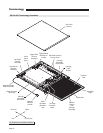
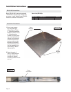
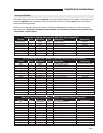
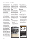
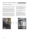
Self-Locking Release Pin: A
self-locking release pin allows
the platform assembly to be
disconnected from the elevation
mechanism, allowing a raised
platform to be manually lowered
in the event of a power failure.
See Photo below. The release
pin should only be used when
the platform will not lower under
electric power, as stated in the
Electrical Method section (next).
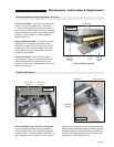
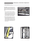
To Manually Extend or Retract
Ramp:
1. Turn (loosen) the manual
release “T” handle 90°.
2. Pull the “T” handle fully out-
ward (3" to 4").
3. Turn (tighten) the “T” handle
90° to secure handle in the
disengaged (unlocked) posi-
tion.
4. Verify mechanism is dis-
engaged (unlocked). View
customer installed sensor LED.
5. Carefully move the platform
in or out to desired location
using the platform Hand Hold.
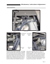
Reengage Carriage Assembly
by Drive Chains:
1. Position the ramp platform
manually so that only 15 cm
is extended out of the cas-
sette.
2. Turn (loosen) the manual
release “T” handle 90°.
3. Push the “T” handle fully
inward until handle contacts
shaft shoulder (3" to 4").
4. Grasp the platform Hand Hold
and move the platform slightly
outward until platform locks
into position (secured by
reengaging the carriage as-
sembly with the drive chains).
Note: Do not push platform
inward to lock as it may then
create a binding condition in
the release mechanism and
will not release easily in the
future
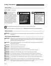
Do not remove!
81823
Push T-handle in fully and
manually move platform in
and out to engage platform
lock before driving vehicle.
Failure to lock platform may
result in unintended platform
deployment. Unintended
platform deployment may
result in serious bodily injury
and/or property damage.
W
A
RNING
Manual Operating Instructions