


Page 18
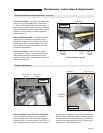
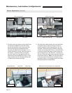
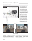
Manual Release System: If the
release cable is difficult to pull to
unlock the system, inspect the
guide and slider shown in Photo T.
Confirm no dirt, metal shavings,
or other foreign debris are pres-
ent and restricting the slider. Also,
check compression spring to verify
the open end of the spring is not
binding the movement of the slider.
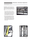
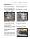
Manual Release Sensor Adjust-
ment: Inspect manual release
sensor to confirm LED is lit when
slider is precisely released from
axle. The distance from the sen-
sor head to the pick-up must be
approximately 4mm or less at this
precise point to ensure Manual
Release Locked/Unlocked signal is
accurate. Adjust distance by mov-
ing sensor in/out via the sensor’s
two locknuts. Operate several
times after adjustment to confirm
new setting is correct.
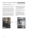
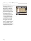
Light Oil can be applied
to chains (small amount)
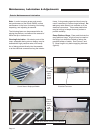
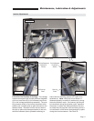
Chain System: The ramp utilizes a 3 chain system.
Two drive chains, left and right, provide the means
for the carriage to travel along. The third chain, in
the rear of the cassette, interlocks the left and right
drive chain to rotate in sequence (or equal time).
During normal operation, none of the 3 chains move.
However, during manual operation of the ramp, all 3
chains travel equal distances. To lubricate, a light oil
may be used on the chains, but should be limited to
reduce the possible buildup of debris.
Right Drive ChainLeft Drive Chain
Connecting or “Timing”
Rear Chain
Maintenance, Lubrication & Adjustments
Cable Compression Sensor Pick-Up Stop Pin Slider Axle
Spring .
Manual Release
(dotted lines represent deployment)
4 MM
Photo T
Photo U Photo V
Interior Adjustments (continued)