1-12 Unpacking and Assembly
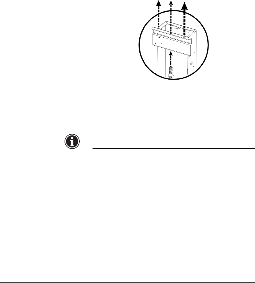
21. Align center hole on each leg (between pins) with center
hole in printer (see Fig. 1-5).
To speed this alignment, you can use a screwdriver inserted
into the holes in the stand and printer.
22. Lower the printer chassis onto the stand.
23. Ensure that the printer lies flat on both of the stand brackets.
Realign if necessary.
Note
The printer must lie flat on the stand brackets to
avoid media feed problems during printer operation.
24. Attach the printer to the stand with one silver #3 screw in the
center hole on each leg (see Fig. 1-5). Tighten all stand
screws securely.
The silver screws provide a ground path between the printer
engine module and the stand. Use an ohmmeter to verify a
ground path between the silver electronics box and the sil-
ver locating pin on the supply & takeup assembly, which is
visible on the stand leg facing the spools. Resistance should
be 5 ohms or less.
If the stand screws are not silver (in other words, “coated”),
the wrong screws were installed. Replace the stand screws
with the silver screws provided by MacDermid ColorSpan.
Fig. 1-5. Stand alignment


