FOX 500 DA6 • Quick Start Guide
Quick Start Guide — FOX 500 DA6 cont’d
QS-2 i
FOX 500 DA6 • Table of Contents
Chapter One • Introduction .................................................... 1-1
About this Manual .................................................................... 1-2
About the FOX 500 DA6 ..........................................................1-2
Features ........................................................................................ 1-4
Chapter Two • Installation and Operation ...................2-1
Mounting the Unit ....................................................................2-2
Tabletop placement ............................................................... 2-2
Rack mounting ....................................................................... 2-2
UL requirements .....................................................................2-2
Mounting instructions............................................................2-3
Furniture mounting the DA ................................................... 2-3
Connections ................................................................................. 2-4
Transmitter rear panel connections ...................................... 2-4
Rear panel serial ports connection ........................................2-8
Alarm outputs connection .....................................................2-9
Front panel Configuration port ............................................ 2-9
Front Panel Indicators ............................................................2-11
System Operation ....................................................................2-12
Chapter Three • Remote Control ........................................3-1
Rear Panel Remote RS-232 Ports .......................................... 3-2
Front Panel Configuration Port .............................................3-3
Simple Instruction Set Control .............................................. 3-3
Host-to-interface communications ....................................... 3-3
Symbol definitions .................................................................3-3
Unit-initiated messages .........................................................3-5
Front panel operations ...........................................................3-5
Error responses ...................................................................... 3-7
Timeout ................................................................................... 3-7
Using the command/response table ..................................... 3-7
Command/response table fro SIS commands ...................... 3-8
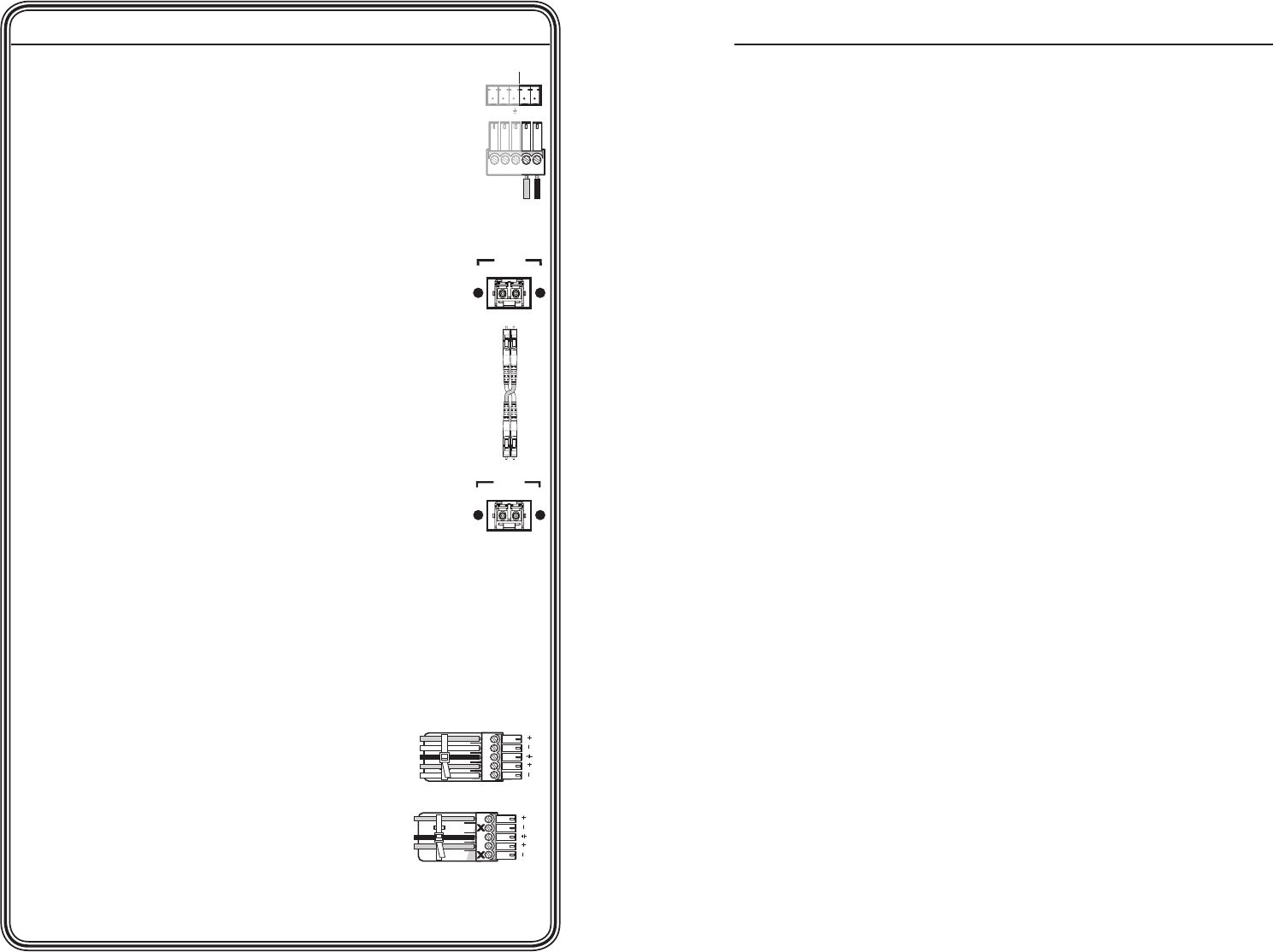
Step 7
For remote monitoring of the status of the Optical 2 link
from the master receiver, connect a locally constructed or
obtained device to the two Alarm poles of the DA's RS-232/
Alarm 5-pole captive screw connector. The DA shorts the
two poles together when no light is detected.
N
The DA's Alarm port reports the status of the
Optical 2 light link.
Step 8
Connect up to six Optical 1 (required) fiber cables between
the DA and receiver(s).
Step 9
If desired, connect the optional Optical 2 fiber cable
between the DA output 1 and the master receiver.
N
Optical 2 is functional only for output 1.
Only Optical 1 is required for video,
audio, and serial command transmission.
Optical 2 is required only to send serial data (such
as commands from the master receiver to the DA
and passed responses from the controlled device
(such as a projector) to the controlling device.
Step 10
Connect 1 or 2 RGBHV, RGBS, or RGsB displays to the receiver(s): to
the RGB Output 15-pin HD connector and/or to the RGB Outputs
BNC connectors.
Step 11
Use the receiver(s)' Alt. Pixels test pattern to set each display's total
pixel and phase for the best picture.
Step 12
Connect balanced or unbalanced stereo
or mono audio devices to the receiver(s):
to the Audio Outputs 3.5 mm mini jack
and/or to the Audio Outputs 5-pole
captive screw connector.
C
Connect the sleeve to ground
(Gnd). Connecting it to a
negative (-) terminal will
damage the audio output
circuits.
REMOTE
RS-232
ALARM
Tx Rx 1 2
OPTICAL
1 2*
*
OPTIONAL FOR
RETURN DATA
LINK
LINK
OPTICAL
2* 1
*
OPTIONAL FOR
RETURN DATA
LINK
LINK
Chapter One • Introduction .................................................... 1-1
Ring
Sleeve(s)
Tip
Tip
Ring
Sleeve(s)
Tip
Tip
Unbalanced Stereo Output
Balanced Stereo Output
NO GROUND.
NO GROUND.
L R
L R


