FOX 500 DA6 • Quick Start Guide
Quick Start Guide — FOX 500 DA6
QS-1
Install, connect, and operate the FOX 500 DA6 as follows:
Step 1
Turn all of the equipment off or disconnect it from the power
source. If desired, mount the DA in a rack or furniture, or place it on
a desktop.
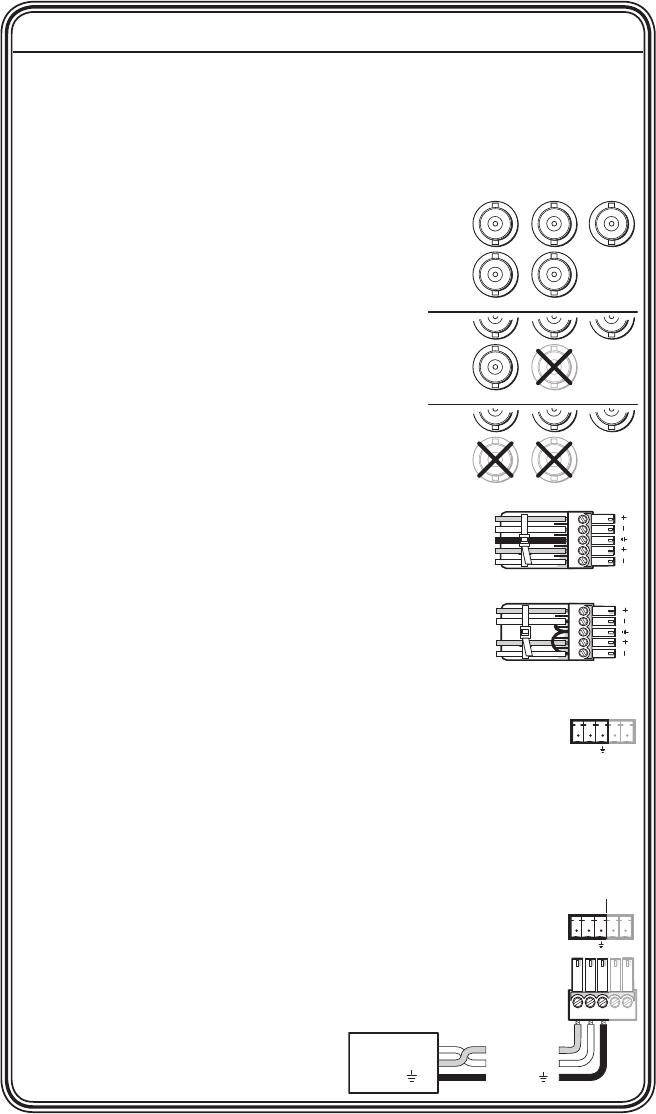
Step 2
Connect a VGA to UXGA source to the
DA: either to the RGB Input 15-pin HD
connector or to the RGB Input BNC
connectors. See the drawing at right to
wire the BNC connectors.
Step 3
If desired, connect a local monitor to the
DA's Buffered Loop-Through 15-pin HD
connector.
Step 4
Connect a balanced or unbalanced, stereo
or mono audio input to the DA: either to
the Audio Inputs 3.5 mm mini jack or to the
Audio Inputs 5-pole captive screw connector.
See the drawing at right to wire the captive
screw connector.
Step 5
If you want the DA to pass serial signals,
such as for serial control of a projector,
connect the master device to the DA and the slave device(s)
to the receiver(s) via three poles of the RS-232 Over Fiber
captive screw connectors on all units.
N
For RS-232 responses (from the master receiver to the DA),
you must install fiber cable Optical 2. See Step 9.
Step 6
For serial control of the DA and receiver, connect
a host device to either unit via three poles of the
Remote RS-232/Alarm captive screw connector or to
either unit's front panel Configuration connector.
RGBHV
H/HV V
RGBS
RGsB,
RsGsBs
H/HV V
H/HV V
R G B
R G B
R G B
Controlling
Device
Receive (Rx)
Transmit (Tx)
Ground ( )
Receive (Rx)
Transmit (Tx)
Ground ( )
Bidirectional
REMOTE
RS-232
ALARM
Tx Rx 1 2
Unbalanced Stereo Input
Balanced Stereo Input
L R L R
Ring
Sleeve (s)
Tip
Sleeve
Tip
Sleeve
Tip
Tip
Ring


