FOX 500 DA6 • Installation and Operation
Installation and Operation
FOX 500 DA6 • Installation and Operation
Mounting the Unit
C
Installation and service must be performed by
authorized personnel only.
The 1U high, full-rack width unit can be placed on a tabletop,
mounted in a rack, or mounted under or through a desk or other
furniture.
Tabletop placement
Affix the four included rubber feet to the bottom of the unit and
place it in any convenient location.
Rack mounting
UL requirements
The following Underwriters Laboratories (UL) requirements
pertain to the installation of the FOX 500 DA6 into a rack
(figure 2-1).
1. Elevated operating ambient — If installed in a closed
or multi-unit rack assembly, the operating ambient
temperature of the rack environment may be greater
than room ambient. Therefore, consider installing the
equipment in an environment compatible with the +122 °F
(+50 °C) maximum ambient temperature (Tma) specified
by the manufacturer.
2. Reduced air flow — Installation of the equipment in a rack
should be such that the amount of air flow required for
safe operation of the equipment is not compromised.
3. Mechanical loading — Mounting of the equipment in
the rack should be such that a hazardous condition is not
achieved due to uneven mechanical loading.
4. Circuit overloading — Consideration should be given to
the connection of the equipment to the supply circuit and
the effect that overloading of the circuits might have on
overcurrent protection and supply wiring. Appropriate
consideration of equipment nameplate ratings should be
used when addressing this concern.
5. Reliable earthing (grounding) — Reliable earthing
of rack-mounted equipment should be maintained.
Particular attention should be given to supply connections
other than direct connections to the branch circuit (such as
the use of power strips).
Mounting instructions
Rack mount the DA as follows:
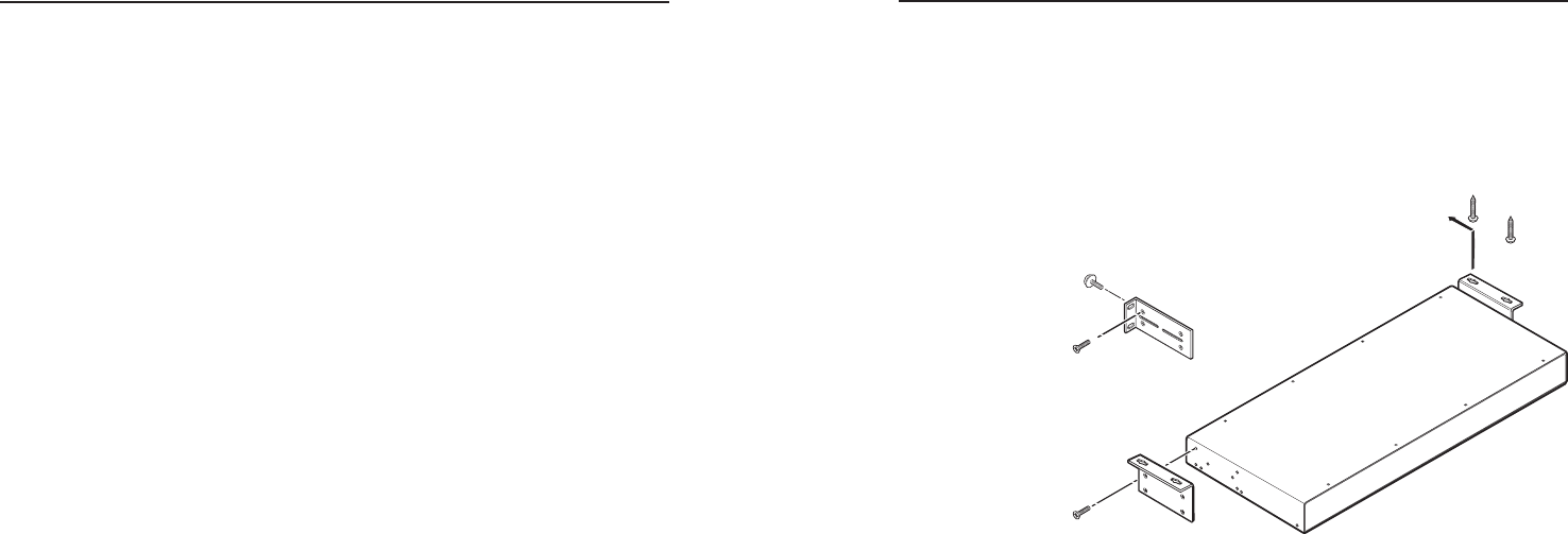
1. Attach the rack mounting brackets to the DA with the
supplied eight #8 machine screws (figure 2-1).
2. Insert the DA into the rack, aligning the holes in the
mounting bracket with those in the rack.
#8 Screw
(4 Plcs)
Each Side
Optional Furniture Mounting Bracket
Supplied Rack Mounting Bracket
Mounting Screws
(2 Plcs)
Each Side
or
Figure 2-1 — Mounting the DA
3. Secure the DA to the rack using the supplied machine
screws.
Furniture mounting the DA
Mount the DA under a table or other horizontal surface with an
optional Extron MBU 149 1U full rack under-desk mounting kit
(part #70-222-01) as follows:
1. Secure the two table/wall mounting brackets to the
unit with the eight machine screws provided in the kit
(figure 2-1).
2. Hold the unit with attached brackets against the underside
of the desk or other furniture. Mark the location of holes
for screws on the underside of the desk.
3. Drill 1/4" (6.4 mm) deep, 3/32" (2 mm) diameter pilot
holes in the table or desk at the marked screw locations
from the underside or inside (concealed side) of the
furniture, where the DA will be located.
4. Insert the four wood screws into the pilot holes. Fasten
each screw into the installation surface until just less than
1/4" of the screw head protrudes.


