FOX 500 DA6 • Installation and Operation
Installation and Operation, cont’d
2-4
FOX 500 DA6 • Installation and Operation
2-5
5. Align the installed screws with the slots in the mounting
brackets, and place the unit against the surface, with the
screws through the bracket slots.
6. Slide the unit slightly forward or back, then tighten all four
screws to fasten it in place.
Connections
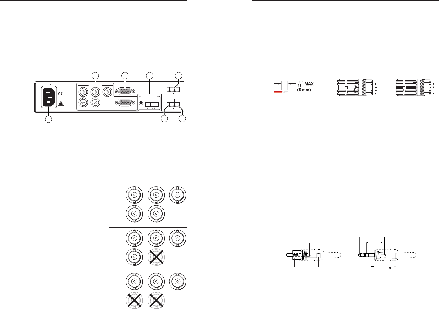
All connectors except the Configuration port are on the rear
panel (figure 2-2 and figure 2-5).
100-240V 0.3A
AUDIO INPUTS
INPUT LOOP THRU
RGB INPUT
R G B
H/HV V
OR
L R
RS-232
OVER FIBER
Tx Rx NA
REMOTE
RS-232
ALARM
Tx Rx 1 2
RGB
50/60 Hz
3
1
2 4
6
5
7
Figure 2-2 — DA’s connectors, left side
a
AC power connector — Plug a standard IEC power cord into
this connector to connect the DA to a 100 VAC to 240 VAC,
50 or 60 Hz power source.
b
RGB Input connectors —
N
Connect an active input to only the BNC connectors or
the 15-pin HD
connector, not
both.
BNC connectors — Connect
an RGBHV, RGBS, RGsB, or
RsGsBs video source to these
BNC connectors. Connect
the cables as shown at right.
15-pin HD connector —
Connect an analog
VGA - UXGA RGB video
source to this 15-pin HD
female connector.
c
Buffered Loop-through
connector — If desired,
connect a local monitor to
this 15-pin HD connector.
d
Audio Input connectors —
3.5 mm mini jack — Plug a stereo mini plug into this connector.
5-pole captive screw connector — Connect a balanced or
unbalanced stereo or mono audio input to this connector. The
connector is included with FOX 500, but you must supply the
audio cable. See figure 2-3 to wire a captive screw connector
for the appropriate input type and impedance level. Use the
supplied tie-wrap to strap the audio cable to the extended tail of
the connector.
L R
Unbalanced Stereo Input
Balanced Stereo Input
Ring
Sleeve (s)
Tip
Sleeve
Tip
Sleeve
Tip
Tip
Ring
Do not tin the wires!
Figure 2-3 — Captive screw connector wiring for
stereo audio input
N
The length of exposed wires is critical. The ideal length
is 3/16” (5 mm).
•
If the stripped section of wire is longer than 3/16”,
the exposed wires may touch, causing a short circuit
between them.
•
If the stripped section of wire is shorter than 3/16”,
wires can be easily pulled out even if tightly fastened
by the captive screws.
N
See figure 2-4 to identify the tip, ring, and sleeve when you
are making connections for the DA from existing audio
cables. A mono audio connector consists of the tip and
sleeve. A stereo audio connector consists of the tip, ring,
and sleeve. The ring, tip, and sleeve wires are also shown
on the captive screw audio connector diagram, figure 2-3.
Tip (+)
Sleeve ( )
Sleeve ( )
Ring (
-
)
Tip (+)
RCA Connector
3.5 mm Stereo Plug Connector
(balanced)
Figure 2-4 — Typical audio connectors
R
RGBHV
G B
H/HV V
RGBS
RGsB,
RsGsBs
R G B
H/HV V
R G B
H/HV V


