Instruction Manual
748213-S
April 2002
Rosemount Analytical Inc. A Division of Emerson Process Management Maintenance and Service 6-7
Model 755R
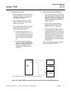
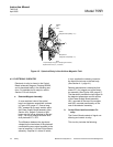
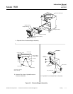
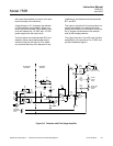
c. Detector
Removal
Prior to removal of the detector, remove
power from instrument and stop flow of
sample gas.
1. Remove the four screws securing the
detector cover plate.
2. Disconnect cable from J12 on the
detector assembly.
NOTE:
Note how the rubber sample lines are
looped into a "long coil". When rein-
stalling the sample lines they must be
configured in the same way. This pre-
caution isolates the detector from the
effects of mechanical vibration. Oth-
erwise vibration waves could travel
upward along the tubing walls, result-
ing in noisy readout.
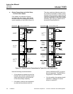
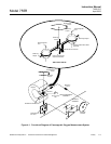
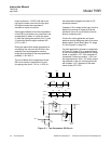
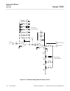
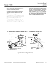
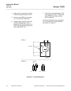
3. Refer to Figure 6-1, page 6-3. Using
needle-nose pliers, squeeze the hose
clamps to disconnect the rubber sam-
ple lines from the metal inlet and out-
let tubes of the detector assembly.
4. Remove the two screws at the bottom
of the detector assembly, slide de-
tector out.
Installation
1. Install replacement detector assembly
and connect cable to J12.
2. Seat the detector assembly firmly
against the magnet pole pieces and
tighten attaching screws.
3. Reconnect rubber sample lines to
metal inlet and outlet tubes on detec-
tor assembly.
4. Apply power to instrument and allow
to warm up approximately one hour.
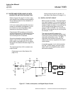
Calibration
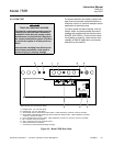
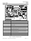
1. On the Control Board, set the front
panel ZERO control (R13) at mid-
range (i.e., five turns from either end).
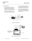
2. Connect a digital voltmeter from the
slider of R9 to chassis ground. With a
steady flow of 50 to 500 cc/min. of ni-
trogen gas passing through the in-
strument, adjust R9 for zero volts.
3. Connect the voltmeter between TP10
and circuit ground (TP7). Adjust front
panel ZERO control (R13) for reading
of exactly zero on voltmeter.
4. With all internal adjustments now
properly set, the instrument may be
calibrated per Section 3-4, page 3-1.
6-6 CONTROL BOARD SETUP
a. Power Supply Test
1. TP7 (circuit ground) is ground point
for all voltage tests.
2. Counterclockwise end of front panel
ZERO potentiometer (R13 on Control
Board): -15 VDC ±0.5 VDC.
3. Clockwise end of ZERO potentiome-
ter: +15 VDC ±5 VDC.
4. Set ZERO potentiometer to obtain a
reading of .0 VDC ±10 mV at slider.
5. Measure TP19: +5 VDC ±0.25 VDC.
b. Detector zero
1. Flow 250 cc/min nitrogen.
2. Monitor TP8, adjust R9 for 0 VDC
±2mV.