Instruction Manual
748213-S
April 2002
Rosemount Analytical Inc. A Division of Emerson Process Management Maintenance and Service 6-3
Model 755R
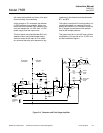
pins 15 and 16 of the detector connector J12,
should be approximately 89 ohms.
If resistance is correct, and the combined re-
sistance is incorrect, heater HR1 may be
open.
To reach the leads of HR1, remove the circuit
board on the heater assembly. Resistance of
HR1 should be approximately 21 ohms.
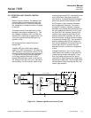
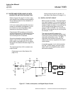
To check operation of the heater circuit, con-
nect a voltmeter across R61 on the Power
Supply Board. Normally, the voltage will be 4
VDC when cold and will drop to approximately
0.4 VDC at control temperature. Temperature
sensor RT1 is mounted in the detector, with
leads accessible at pins 10 and 11 of detector
connector J12. The sensor resistance should
be 1M ohms at 25°C and approximately 149K
ohms at operating temperature of 65°C.
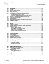
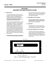
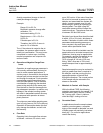
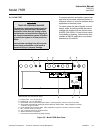
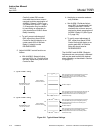
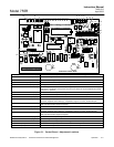
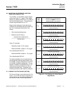
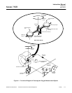
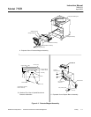
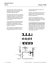
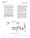
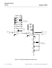
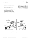
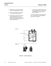
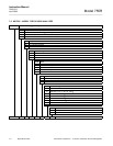
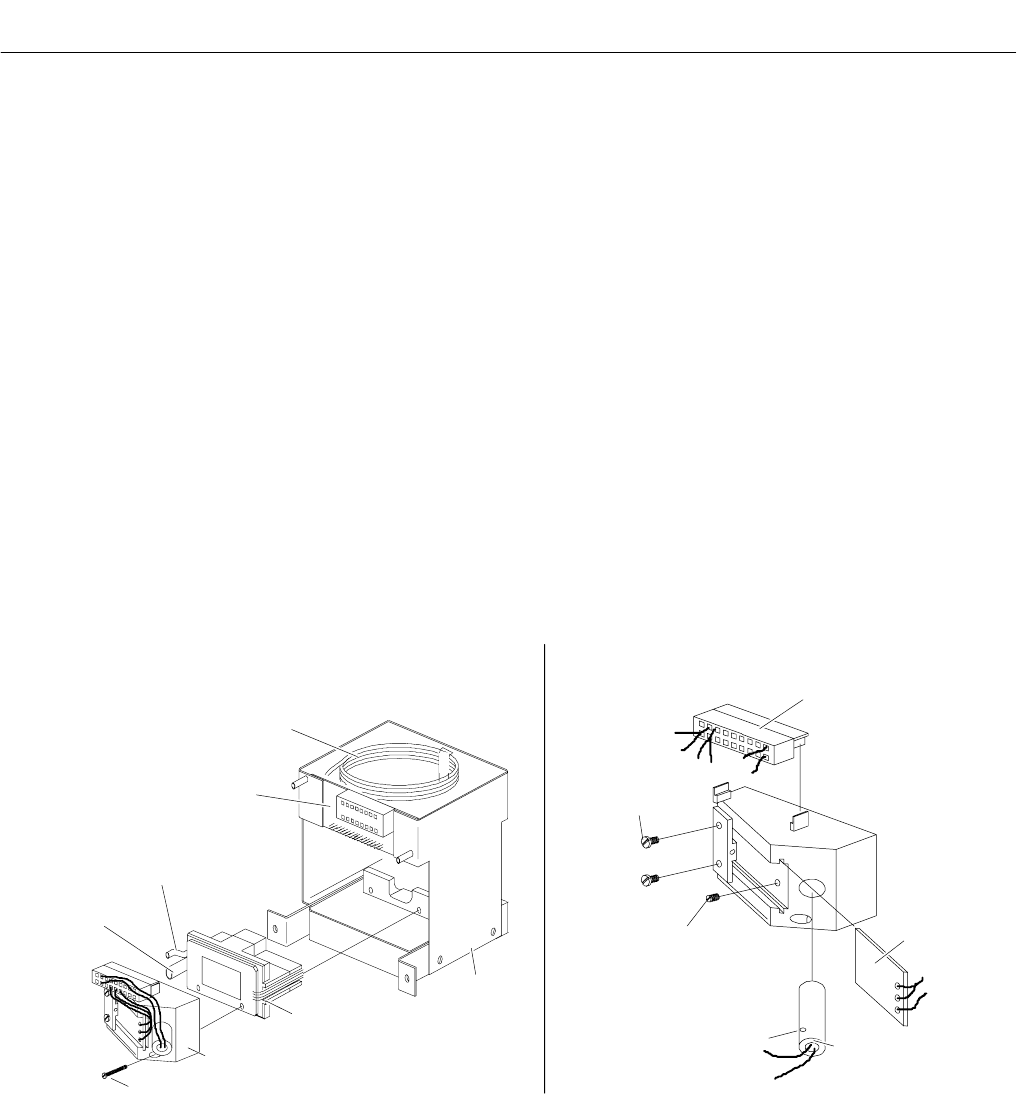
Figure 6-1. Detector/Magnet Assembly
Dual
Photocell
Connector
J12
Lamp Retaining
Set Screw
Photocell
Lock Screws (2)
Lamp Viewing
Hole
Source Lamp
Assembly
Mounting Screws (2)
Optical Bench Assembly
Detector Assembly
Magnet
Assembly
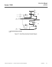
Sample Out-
let Tube
Sample Inlet
Tube
Sample Pre-Heating
Coil
Connector
Board
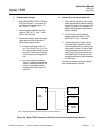
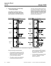
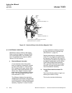
A. Detector/Magnet Assembly - Exploded View B. Optical Bench - Exploded View