Instruction Manual
748213-S
April 2002
6-6 Maintenance and Service Rosemount Analytical Inc. A Division of Emerson Process Management
Model 755R
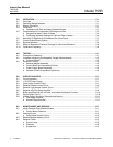
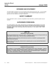
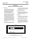
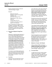
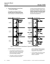
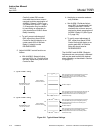
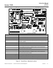
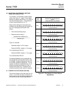
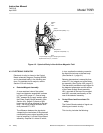
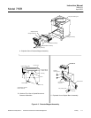
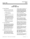
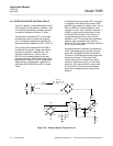
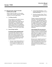
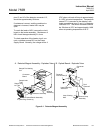
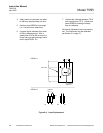
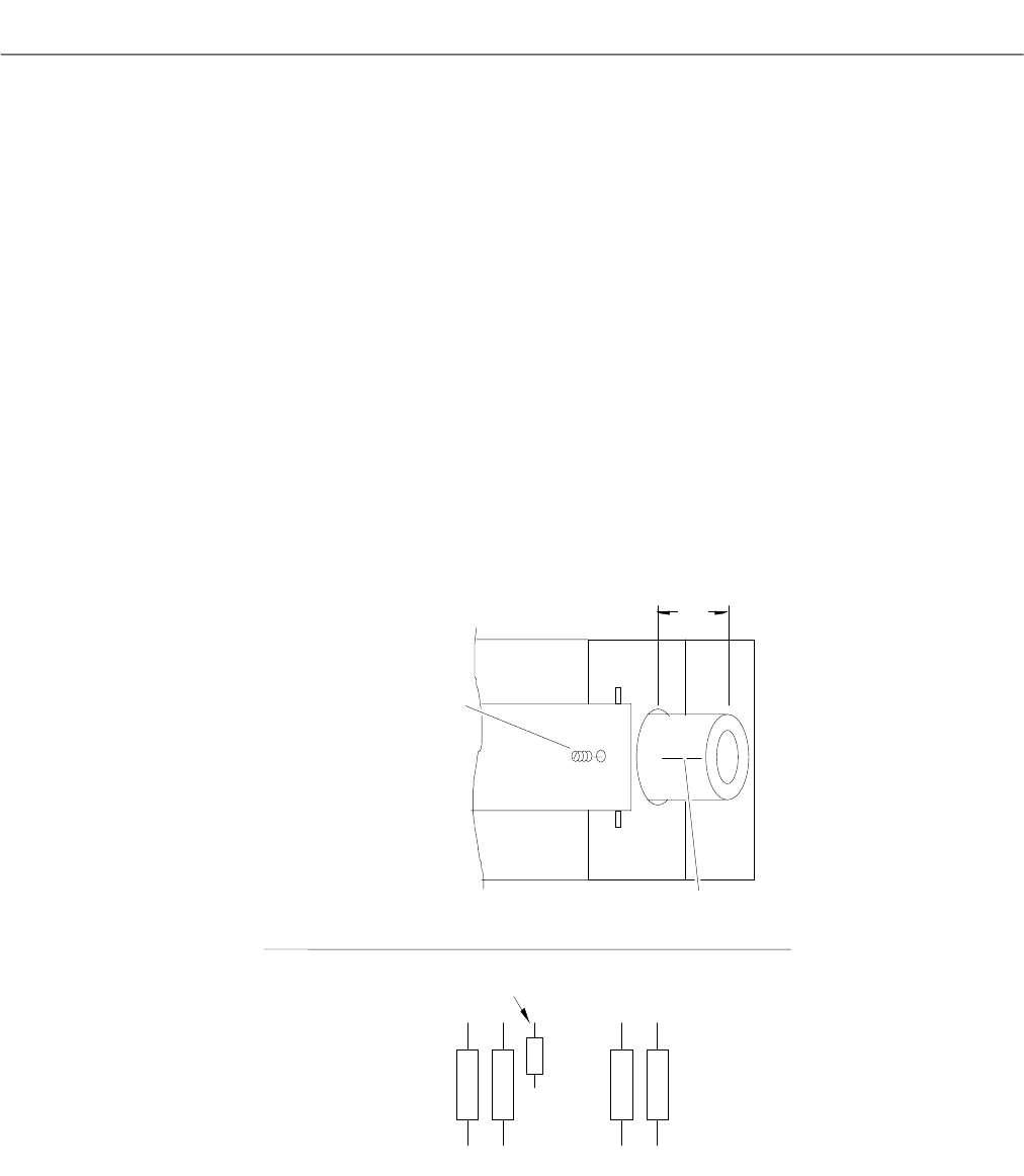
Red Mark for
li
nment
1/4"
Set Screw
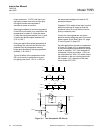
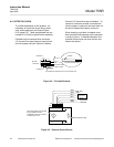
C8
C1
R10
Voltmeter
Lead
R8
R7
DETAIL A
DETAIL B
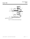
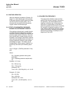
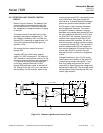
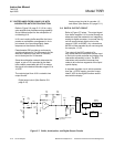
4. Apply power to instrument and allow
to warm-up approximately one hour.
5. Set front panel ZERO at mid-range
(i.e., five turns from either end).
6. Connect digital voltmeter from slider
of R9 to chassis ground. With a
steady flow of 50 to 500 cc/min of ni-
trogen zero gas going through instru-
ment, adjust R9 for 0 V.
7. Connect the voltmeter between TP10
and circuit ground (TP7). Adjust front
panel ZERO for reading of exactly
zero on voltmeter.
All internal adjustments are now properly
set. The instrument may be calibrated
per Section 3-4, page 3-1.
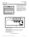
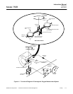
Figure 6-4. Lamp Replacement