Instruction Manual
748213-S
April 2002
Rosemount Analytical Inc. A Division of Emerson Process Management Installation 2-9
Model 755R
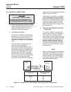
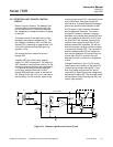
Alarm 1 and Alarm 2 output through the
654019 Alarm Relay Assembly is pro-
vided by two identical single-pole, dou-
ble-throw relays. These relay contacts are
rated at the following values:
5 amperes 240 VAC resistive
1 ampere 240 VAC inductive
5 amperes 120 VAC resistive
3 amperes 120 VAC inductive
5 amperes 30 VDC resistive
3 amperes 30 VDC inductive
Removal of AC power from the analyzer
(such as power failure) de-energizes both
relays, placing them in alarm condition.
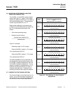
Switching characteristics of the Alarm 1
and Alarm 2 relays are as follows:
The Alarm 1 relay coil is de-energized
when the display moves downscale
through the value that corresponds to
setpoint minus deadband. This relay coil
is energized when the display moves up-
scale through the value that corresponds
to setpoint plus deadband.
The Alarm 2 relay coil is de-energized
when the display moves upscale through
the value that corresponds to the setpoint
plus deadband. This relay coil is ener-
gized when the display moves downscale
through the value that corresponds to
setpoint minus deadband.
Both the ALARM 1 and ALARM 2 func-
tions generally incorporate automatic rest.
When the display goes beyond the pre-
selected limits, the corresponding relay is
de-energized. When the display returns
within the acceptable range, the relay is
turned on.
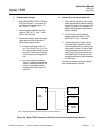
The ALARM 1 and/or ALARM 2 alarm
functions may be converted to manual re-
set. The conversion requires the substitu-
tion of an external pushbutton or other
momentary contact switch for the jumper
that connects the RESET terminals on the
Alarm Relay Assembly. If the corre-
sponding relay is now de-energized (i.e.,
in alarm condition), the relay remains
de-energized until the operator momen-
tarily closes the switch.
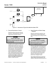
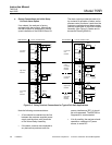
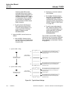
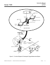
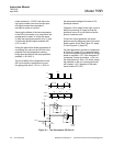
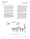
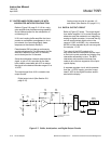
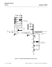
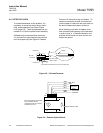
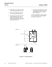
By appropriate connection to the dou-
ble-throw relay contacts, it is possible to
obtain either a contact closure or a con-
tact opening for an energized relay. Also,
either a contact closure or a contact
opening may be obtained for a
de-energized relay. It is important, for
fail-safe applications, that the user under-
stands what circuit conditions are desired
in event of power failure and the resultant
relay de-energization. Relay contacts
should then be connected accordingly
(See Figure 2-5, page 2-8).
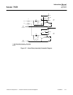
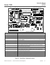
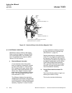
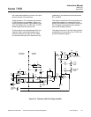
The ALARM 1 and ALARM 2 circuits have
independent setpoint and deadband ad-
justments (See Figure 3-1, page 3-3). Ini-
tially, the ALARM 1 and ALARM 2
Setpoint Adjustments must be calibrated
by means of the ALARM 1 and ALARM 2
Calibration Adjustments by the following
procedure:
1. Set RANGE Select in a position ap-
propriate to the span standard gas.
2. Inject span standard gas through ana-
lyzer at 50 to 500 cc/min.
3. Verify that ALARM 1 and ALARM 2
Deadband Adjustments (See Figure
3-1, page 3-3) are set for minimum
value (turned fully counterclockwise).
These potentiometers should be fac-
tory-set for minimum deadband. Both
potentiometers MUST REMAIN at this
setting throughout calibration of the
alarm setpoint adjustments.
4. Adjust ALARM 1 control function as
follows:
a. With ALARM 1 Setpoint Adjust-
ment at 100% (i.e., position 10 on
dial), adjust front panel SPAN
Control so that the display or re-
corder reads exactly fullscale.
b. Set ALARM 1 Calibrate Adjust-
ment (R63) to its clockwise limit.