Instruction Manual
748213-S
April 2002
Rosemount Analytical Inc. A Division of Emerson Process Management Operation 3-3
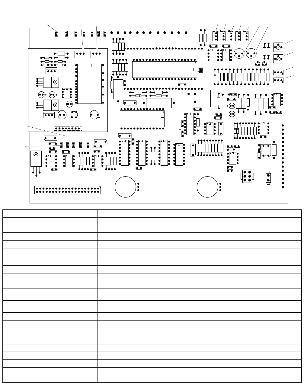
Model 755R
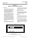
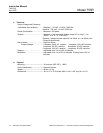
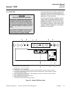
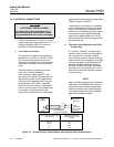
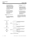
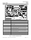
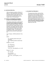
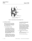
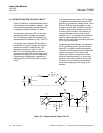
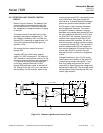
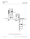
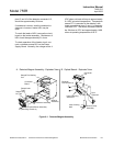
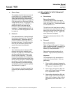
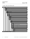
1. RECORDER OUTPUT selector plug Provides selectable output of 10 mV, 100 mV, 1 V or 5 V for a voltage recorder.
2. DIGITAL READOUT (R100) Calibration of digital readout.
3. AMPLIFIER U8 ZERO (R29) Initial factory zeroing of amplifier U8.
4. RESPONSE TIME (R30) Adjustment of electronic response time.
5. FULLSCALE OUTPUT (R88) Setting fullscale for 1 V, 0.1 V and 10 mV outputs.
6. DETECTOR COARSE ZERO (R9) Coarse adjustment of detector zero by shifting the position of the detector within the mag-
netic field. It is adjusted during factory checkout, and does not require readjustment except
if detector is replaced.
7. CURRENT OUTPUT ZERO (R1) Located on Current Output Board, adjustment for zero-level current output, i.e., 4mA or 0mA
8. CURRENT OUTPUT SPAN (R2) Located on Current Output Board, adjustment for fullscale current output: 20mA
9. ALARM 2 CALIBRATION (R67) Initial calibration of ALARM 2 circuit.
10. ALARM 2 SETPOINT (R68) Continuously variable adjustment of setpoint for ALARM 2 circuit, for actuation of external,
customer supplied control device(s). Adjustment range is 0 to 100% of fullscale span.
11. ALARM 2 DEADBAND (R78) Adjustment of ALARM 2 deadband circuit from 1% to 20% of fullscale. Deadband is essen-
tially symmetrical with respect to setpoint.
12. ALARM 1 CALIBRATION (R63) Initial calibration of ALARM 1 circuit.
13. ALARM 1 SETPOINT (R64) Continuously variable adjustment of setpoint for ALARM 1 circuit, for actuation of external,
customer supplied control device(s). Adjustment range is 0 to 100% of fullscale span.
14. ALARM 1 DEADBAND (R73) Adjustment of ALARM 1 deadband circuit from 1% to 20% of fullscale. Deadband is essen-
tially symmetrical with respect to setpoint.
15. OUTPUT RANGE selector plug Selectable fullscale output range.
16. DETECTOR ISOLATION plug For servicing and testing of the Control Board.
DIGITAL DISPLAY Display (viewed on front panel) indicates oxygen content of sample.
ZERO control (R13) Accessible on front panel, use to establish zero-calibration point.
SPAN control (R20) Accessible on front panel, use to establish span calibration point.
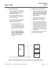
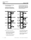
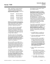
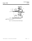
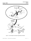
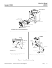
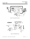
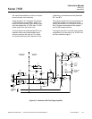
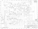
Figure 3-1. Control Board - Adjustment Locations
E18
5%
1%
SPAN
E10
E12 E14 E16 E20
100% 50%
25%
10% 2.5%
E24
E23E9
E11 E13 E15
E17
E19
TP5 TP6
TP7TP8 TP9 TP10TP11 TP16 TP17 TP18
TP19
TP20
U15
U12
BL
U17
U11
CR1
CR2
R1
R2
R3
R4
R5
R6
C31
R13
CW
S
CCW
C28 C27
C30
C29
U8
C26
J5
J6
J4
C64
E
U19
U20
R68
R64
R79R74
R63
R67
Q1
Q2
E
R11 R66 R77 R80 R82 R72 R70
R73
CR3 R12 R76 R69 R81 R75 R71 R85
R78
R101
C38 C41
R8
C17
C18
C16
C8
C1
R7
R10 C66
U2
C10
C9
C6
C37
C39
C36
U10
C4
U1
C5
C2
C7C3
1
2
3
4
5
6
7
8
9
10
11
12
13
14
15
16
C67
R89
R90
R88 R30 R29 R100
C63
R9
CW
S
CCW
SPAN
ZERO
652830 SIGNAL CONTROL BOARD
R36
R31
R61
R39
R38
R28
R37
R25
R27
C50
C44
C51
R54
R52
R87
R53
R82
R47
R84
R85
R86
R102
R49
R40
C48
U11
CR1
CR2
R1
R2
R3
R4
R5
R6
C31
R13
CW
S
CCW
C28 C27
C30
C29
U8
C26
J5
J6
J4
C64
E
U19
U20
R68
R64
R79R74
R63
R67
Q1
Q2
E
R11 R66 R77 R80 R82 R72 R70
R73
CR3 R12 R76 R69 R81 R75 R71 R85
R78
C38 C41
R8
C17
C16
C8
C1
R7
R10 C66
U2
C10
C9
C6
C37
C39
C36
U10
C4
C5
C2
C7C3
1
2
3
4
5
6
7
8
9
10
11
12
13
14
15
16
C67
R89
R90
R88 R30 R29 R100
C63
R9
R20
CW
S
CCW
SPAN
ZERO
652830 SIGNAL CONTROL BOARD
R36
R31
R61
R39
R38
R28
R37
R25
R27
C50
C65
R56
R55
U21
U14
C53
C55
R50
R57
R58
R59
R60
R21
R2
R2
R2
C12
C13
C61
C59
C60
C56
C58
U18
C57
U16
C49
U13
U4
C14
E22 E2 E4 E6 E8
E21 E1 E3 E5 E7
5V 1V .1V .01V
J2
U4
R2 R1
R3
R4
R5
R6
R8
R9
CR2
U6
I G O
U3
U2
1
2
3
4
I
G
O
C5
C4
C2
U5
I G O
C3 CR1 C1
U1
J1
C68
T1
R43
CR5
T1
R42
CR4
C45
+
15
8
7
1
16
5 4
3
2
6 10
13
12
9
14
11