Instruction Manual
748213-S
April 2002
2-4 Installation Rosemount Analytical Inc. A Division of Emerson Process Management
Model 755R
directly proportional change in the indi-
cated percentage of oxygen.
Example:
Range, 0% to 5% O
2.
Barometric pressure change after
calibration, 1%.
Instrument reading, 5% O
2
.
Readout error = 0.01 x 5% O
2
=
0.05% O
2
.
Fullscale span is 5% O
2.
Therefore, the 0.05% O
2
error is
equal to 1% of fullscale.
Thus, if the exhaust is vented to the at-
mosphere, the pressure effect must be
taken into consideration. This may be ac-
complished in various ways, including
manual computation and computer cor-
rection of data.
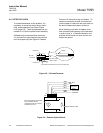
d. Operation at Negative Gauge Pres-
sures
Operation at negative gauge pressures is
not normally recommended, but may be
used in certain special applications. A
suction pump is connected to the analyzer
exhaust port to draw sample into the inlet
and through the analyzer. Such operation
necessitates special precautions to en-
sure accurate readout. First is the basic
consideration of supplying the standard
gases to the analyzer at the same pres-
sure that will be used for the sample dur-
ing subsequent operation. In addition, any
leakage in the sample handling system
will result in decreased readout accuracy
as compared with operation at atmos-
pheric pressure.
The minimum permissible operating pres-
sure is 5 psig vacuum (34.5 kPa vacuum).
Operation of the analyzer below this limit
may damage the detector, and will void
the warranty.
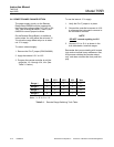
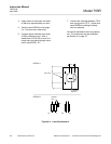
e. Flow Rate
Operating limits for sample flow rate are
as follows: minimum, 50 cc/min; maxi-
mum, 500 cc/min. A flow rate of less than
50 cc/min is too weak to sweep out the
detector and associated flow system effi-
ciently. Incoming sample may mix with
earlier sample, causing an averaging or
damping effect. Too rapid a flow will
cause back pressure that will affect the
readout accuracy. The optimum flow rate
is between 200 and 300 cc/min.
Deviation from the set flow should be held
to within 10% or 20 cc/min, whichever is
smaller. If deviation is held to within these
parameters and operating pressure re-
mains constant, zero and span drift will
remain within specification limits.
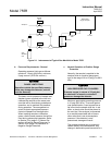
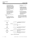
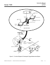
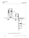
The analyzer should be installed near the
sample source to minimize transport time.
Otherwise, time lag may be appreciable.
For example, assume that sample is sup-
plied to the analyzer via a 100-foot
(30.5 m) length of 1/4-inch (6.35 mm)
tubing. With a flow rate of 100 cc/min,
sample transport time is approximately 6
minutes.
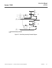
Sample transport time may be reduced by
piping a greater flow than is required to
the analyzer, and then routing only the
appropriate portion of the total flow
through the analyzer. The unused portion
of the sample may be returned to the
stream or discarded.
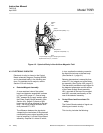
f. Materials in Contact with Sample
Within the Model 755R, the following
materials are exposed to the sample: 316
stainless steel, glass, titanium, Paliney
No.7, epoxy resin, Viton-A, platinum,
nickel and MgF
2
coating on mirror.
g. Corrosive Gases
In applications where the sample stream
contains corrosive gases, a complete
drying of the sample is desirable, as most
of these gases are practically inert when
totally dry. For corrosive applications
consult the factory.