Instruction Manual
748213-S
April 2002
5-6 Circuit Analysis Rosemount Analytical Inc. A Division of Emerson Process Management
Model 755R
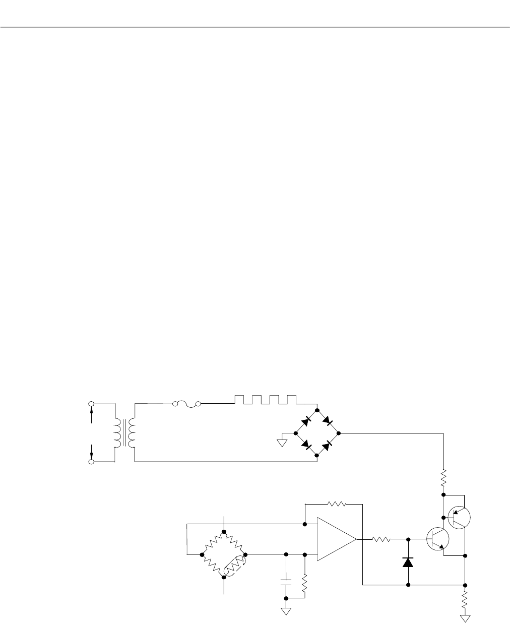
5-4 DETECTOR HEATER CONTROL CIRCUIT
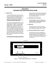
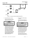
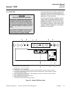
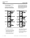
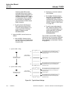
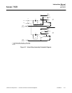
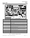
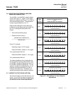
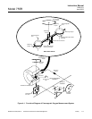
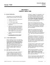
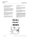
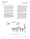
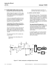
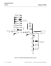
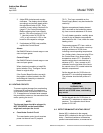
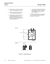
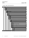
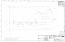
Figure 5-4 below is a simplified heater control
circuit drawing for the detector. Heaters 1 and
2 are actually connected in parallel and have
a combined resistance of about 17 ohms.
The thermistor resistance (RT1) in the resis-
tance bridge varies inversely with tempera-
ture. The bridge is designed to maintain the
temperature of the detector at 150°F (65.5°C).
The junction point between R55 and R56 is
maintained at a specific voltage since these
resistances maintain a definite ratio. The
thermistor resistance is 149 K at 150F
(65.5°C) and increases rapidly as the tem-
perature decreases. R59 in this bridge circuit
represents the setpoint value for temperature.
Suppose that, at temperature, resistance of
the bridge (R55, R56, R59 and RT1) equals
149 K.
If the temperature goes down, RT1 increases
in resistance and causes the junction of RT1
and R59 to go positive in voltage value. Since
R55 and R56 are of equal resistance, their
junction is at zero volts. Therefore, terminal 3
of AR6 is more positive than terminal 2 and
the base of Q2 is positive. Q2 conducts, al-
lowing alternating current to flow through
heaters 1 and 2. The voltage drop across the
heaters, when completely cold, would be
about 20 VAC and, when controlling, would be
AC of very low amplitude.
As the temperature increases, the resistance
of RT1 decreases and the junction point be-
tween RT1 and R59 becomes less positive.
Terminal 3 of AR6 becomes less positive with
respect to terminal 2. The output of AR
causes Q2 and Q3 to conduct less. When
terminal 3 equals terminal 2, or is less than
terminal 2, the output of AR6 is zero or less.
Q2 and Q3 do not conduct and the heater
would not be supplying heat energy to the
detector.
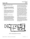
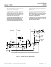
Figure 5-4. Detector Heater Control Circuit
25 VAC
C31
.01uF
-
+
U6
R56
149K
Q2
CR12
120 V
RMS
Q3
R60
100
R61
2.0
R62
1K
R58
5M
R88
5M
R55
700K
R59
700K
RT1
+15V
-15V
2
3
6
HR1 +2
F1
CR6
WO4