


Trace Oxygen Analyzer Installation
Teledyne Analytical Instruments 23
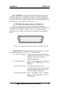
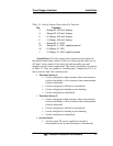
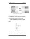
Table 3-1: Analog Output Connections Pin Function
Pin Function
3 + Range ID, 4-20 mA, floating
4 – Range ID, 4-20 mA, floating
5 + % Range, 4-20 mA, floating
6 – % Range, 4-20 mA, floating
8 + Range ID, 0-1 VDC
23 – Range ID, 0-1 VDC, negative ground
24 + % Range, 0-1 VDC
7 – % Range, 0-1 VDC, negative ground
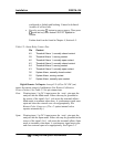
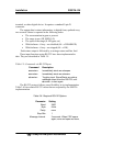
Alarm Relays: The nine alarm-circuit connector pins connect to
the internal alarm relay contacts. Each set of three pins provides one set
of Form C relay contacts. Each relay has both normally open and
normally closed contact connections. The contact connections are shown
in Table 3-2. They are capable of switching up to 3 amperes at 250 V ac
into a resistive load. The connectors are:
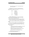
Threshold Alarm 1:
Can be configured as high (actuates when concentration
is above threshold), or low (actuates when concentration
is below threshold).
Can be configured as failsafe or non-failsafe.
Can be configured as latching or non-latching.
Can be configured out (defeated).
Threshold Alarm 2:
Can be configured as high (actuates when concentration
is above threshold), or low (actuates when concentration
is below threshold).
Can be configured as failsafe or non-failsafe.
Can be configured as latching or non-latching.
Can be configured out (defeated).
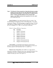
System Alarm:
Actuates when DC power supplied to circuits is
unacceptable in one or more parameters. Permanently