


Trace Oxygen Analyzer Installation
Teledyne Analytical Instruments 21
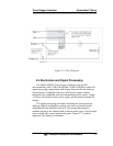
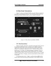
EXHAUST OUT:
Exhaust connections must be consistent with the hazard level of the
constituent gases. Check Local, State, and Federal laws, and ensure that
the exhaust stream vents to an appropriately controlled area if required.
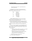
ZERO IN and SPAN IN (Optional):
These are additional ports for inputting span gas and zero gas.
There are electrically operated valves inside for automatic switching
between sample and calibration gases. These valves are completely
under control of the 3000T Electronics. They can be externally
controlled only indirectly through the Remote Cal Inputs, described
below.
Pressure, flow, and safety considerations are the same as prescribed
for the SAMPLE IN inlet, above.
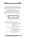
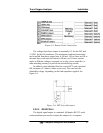
3.3.2 Electrical Connections
For safe connections, no uninsulated wiring should be able to come
in contact with fingers, tools or clothing during normal operation.
CAUTION: USE SHIELDED CABLES. ALSO, USE PLUGS THAT
PROVIDE EXCELLENT EMI/RFI PROTECTION. THE
PLUG CASE MUST BE CONNECTED TO THE CABLE
SHIELD, AND IT MUST BE TIGHTLY FASTENED TO
THE ANALYZER WITH ITS FASTENING SCREWS.
ULTIMATELY, IT IS THE INSTALLER WHO ENSURES
THAT THE CONNECTIONS PROVIDE ADEQUATE
EMI/RFI SHIELDING.
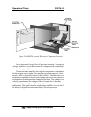
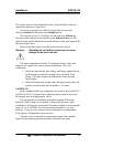
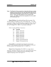
3.3.2.1 PRIMARY INPUT POWER
The power cord receptacle and fuse block are located in the same
assembly. Insert the power cord into the power cord receptacle.
CAUTION: POWER IS APPLIED TO THE INSTRUMENT'S
CIRCUITRY AS LONG AS THE INSTRUMENT IS
CONNECTED TO THE POWER SOURCE. THE RED
SWITCH ON THE FRONT PANEL IS FOR SWITCHING
POWER ON OR OFF TO THE DISPLAYS AND OUT-
PUTS ONLY.
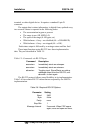
The universal power supply requires a 85–250 V ac, 47-63 Hz
power source.