


Trace Oxygen Analyzer
Teledyne Analytical Instruments xi
List of Figures
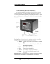
Figure 1-1: Model 3000TA Front Panel ........................................... 3
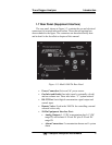
Figure 1-2: Model 3000 TA Rear Panel ........................................... 5
Figure 2-1: Micro-Fuel Cell .............................................................. 8
Figure 2-2. Cross Section of a Micro-Fuel Cell (not to scale) .......... 8
Figure 2-3. Characteristic Input/Output Curve for a Micro-Fuel
Cell ............................................................................. 11
Figure 2-4: Piping Layout and Flow Diagram for Standard Model . 12
Figure 2-5: Flow Diagram .............................................................. 13
Figure 2-6: 3000TA Internal Electronic Component Location ........ 14
Figure 2-7: Block Diagram of the Model 3000TA-EU Electronics . 15
Figure 3-1: Front Panel of the Model 3000TA ............................... 18
Figure 3-2: Required Front Door Clearance .................................. 18
Figure 3-3: Rear Panel of the Model 3000TA ................................ 19
Figure 3-4: Equipment Interface Connector Pin Arrangement ....... 22
Figure 3-5: Remote Probe Connections ........................................ 27
Figure 3-6: FET Series Resistance ............................................... 27
Figure 5-1: Removing the Micro-Fuel ............................................ 59
Figure 5-2: Removing Fuse Block from Housing ........................... 61
Figure 5-3: Installing Fuses ........................................................... 62
Figure 5-4: Rear-Panel Screws ..................................................... 64
Figure A-1: Single and Dual 19" Rack Mounts .............................. 70