


Operational Theory 3000TA- EU
Teledyne Analytical Instruments 12
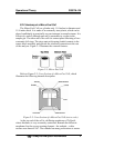
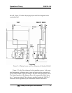
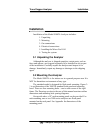
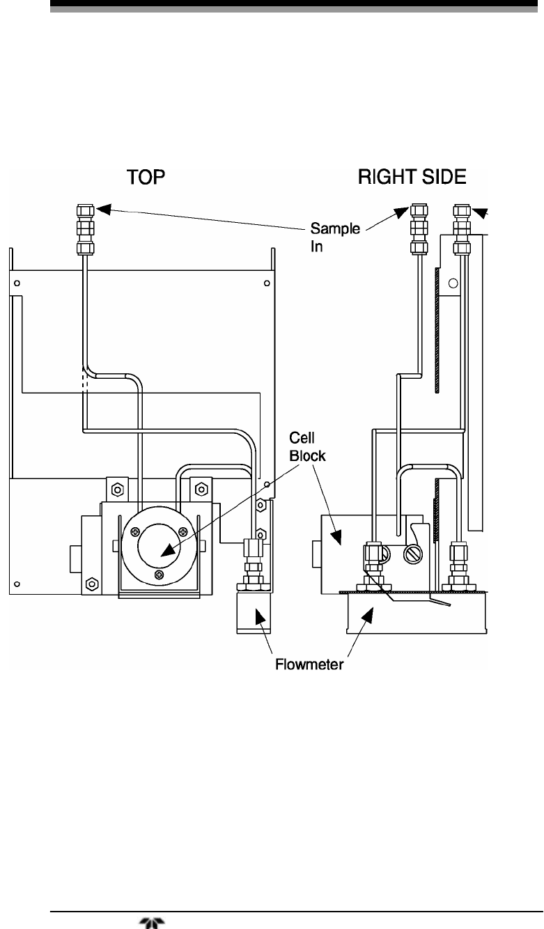
the cell. Figure 2-4 shows the piping layout and flow diagram for the
standard model.
Figure 2-4: Piping Layout and Flow Diagram for Standard Model
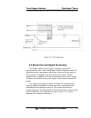
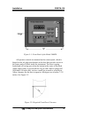
Figure 2-5 is the flow diagram for the sampling system. In the stan-
dard instrument, calibration gases (zero and span) can be connected di-
rectly to the Sample In port by teeing to the port with appropriate valves.
The shaded portion of the diagram shows the components added when
the –C option is ordered. The valving is installed inside the 3000TA-C
enclosure and is regulated by the instruments internal electronics.